|
|
AR-651 (serv.man11)
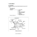
Laser optical unit
Service Manual
|
9
|
877.36 KB
|
|
|
AR-651 (serv.man22)
Unpacking and installation
Service Manual
|
11
|
1.2 MB
|
|
|
AR-651 (serv.man21)
Printed wiring boards
Service Manual
|
7
|
4.21 MB
|
|
|
AR-651 (serv.man20)
Power supply unit
Service Manual
|
8
|
110.03 KB
|
|
|
AR-651 (serv.man19)
RADF (Document feeder)
Service Manual
|
91
|
3.35 MB
|
|
|
AR-651 (serv.man17)
Fuser unit
Service Manual
|
21
|
647.22 KB
|
|
|
AR-651 (serv.man16)
Transfer transporter unit
Service Manual
|
10
|
462.6 KB
|
|
|
AR-651 (serv.man15)
Developer unit
Service Manual
|
21
|
585.54 KB
|
|
|
AR-651 (serv.man14)
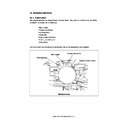
Drum cleaner unit
Service Manual
|
10
|
281.09 KB
|
|
|
AR-651 (serv.man13)
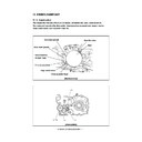
Process section
Service Manual
|
12
|
226.72 KB
|
|
|
AR-651 (serv.man12)
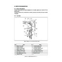
Paper feeding section
Service Manual
|
25
|
847.82 KB
|
|
|
AR-651 (serv.man10)
Scanning section
Service Manual
|
14
|
100.65 KB
|
|
|
AR-651 (serv.man9)
Control panel
Service Manual
|
12
|
199.17 KB
|
|
|
AR-651 (serv.man8)
General operations
Service Manual
|
14
|
97.83 KB
|
|
|
AR-651 (serv.man7)
Copy process
Service Manual
|
11
|
177.81 KB
|
|
|
AR-651 (serv.man6)
Component layout functions
Service Manual
|
30
|
1.25 MB
|
|
|
AR-651 (serv.man5)
Front cover, precautions and contents
Service Manual
|
5
|
80.44 KB
|
|
|
AR-651 (serv.man4)
AR651 810-Service Handbook
Service Manual
|
127
|
17.7 MB
|
|
|
AR-651 (serv.man3)
AR651 810-Circuit Diagrams
Service Manual
|
127
|
9.77 MB
|
|
|
AR-651 (serv.man23)
Complete service manual
Service Manual
|
127
|
14.46 MB
|
|
|
AR-651 (serv.man25)
AR651 810 Operation Manuals
User Manual / Operation Manual
|
127
|
3.81 MB
|
|
|
AR-651 (serv.man24)
AR651 810-Parts Guide
Service Manual / Parts Guide
|
127
|
22.77 MB
|
|
|
AR-651 (serv.man2)
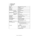
Specifications
Service Manual / Specification
|
15
|
120.76 KB
|
|
|
AR-651 (serv.man51)
The improvement for image glossy lines due to grease of cleaning roller.
Service Manual / Technical Bulletin
|
2
|
82.16 KB
|
|
|
AR-651 (serv.man43)
Change of the PWB unit in the laser optical unit.
Service Manual / Technical Bulletin
|
1
|
104.34 KB
|
|
|
AR-651 (serv.man44)
Change of torque limiter.
Service Manual / Technical Bulletin
|
1
|
91.88 KB
|
|
|
AR-651 (serv.man45)
Parts change information regarding the lower frame and inversion open guide part 1.
Service Manual / Technical Bulletin
|
2
|
155.27 KB
|
|
|
AR-651 (serv.man46)
Measure to prevent breakage of one way bearing on cleaning web.
Service Manual / Technical Bulletin
|
3
|
272.27 KB
|
|
|
AR-651 (serv.man47)
Revision of illustration of 4 Lower frame section in the parts guide
Service Manual / Technical Bulletin
|
2
|
353.24 KB
|
|
|
AR-651 (serv.man48)
ROM upgrade ... (5)
Service Manual / Technical Bulletin
|
10
|
153.94 KB
|
|
|
AR-651 (serv.man49)
Change of parts to extend service life of paper feed section roller.
Service Manual / Technical Bulletin
|
6
|
480.62 KB
|
|
|
AR-651 (serv.man50)
The improvement for displaying tandem LCF check paper
Service Manual / Technical Bulletin
|
6
|
1.64 MB
|
|
|
AR-651 (serv.man32)
Correction of SRAM parts code.
Service Manual / Technical Bulletin
|
1
|
12.92 KB
|
|
|
AR-651 (serv.man52)
The improvement for waving vertical lines in the rear side of the copy image
Service Manual / Technical Bulletin
|
2
|
240.2 KB
|
|
|
AR-651 (serv.man53)
Correction for loss of image 1 3 from the trail edge
Service Manual / Technical Bulletin
|
1
|
12.31 KB
|
|
|
AR-651 (serv.man54)
Countermeasure for background CD3 error near toner empty-toner recycle pipe blockage.
Service Manual / Technical Bulletin
|
2
|
32.94 KB
|
|
|
AR-651 (serv.man55)
Change of part code of PWB unit listed in the fusing drive section in the part guide 24 .
Service Manual / Technical Bulletin
|
1
|
22.35 KB
|
|
|
AR-651 (serv.man56)
Correction of parts codes of pulleys on the reversion drive unit listed in the part guide 13 .
Service Manual / Technical Bulletin
|
1
|
14.8 KB
|
|
|
AR-651 (serv.man57)
Improvement carried out to stop EB5 jam, due to over running of the paper stop position.
Service Manual / Technical Bulletin
|
1
|
8.1 KB
|
|
|
AR-651 (serv.man58)
ROM upgrading (4)
Service Manual / Technical Bulletin
|
8
|
46.83 KB
|
|
|
AR-651 (serv.man59)
Required attention when installing the OPC drum to the cleaner unit.
Service Manual / Technical Bulletin
|
2
|
855.9 KB
|
|
|
AR-651 (serv.man41)
Change of the PWB unit in section 88 (RADF hinge) of the parts guide.
Service Manual / Technical Bulletin
|
1
|
102.84 KB
|
|
|
AR-651 (serv.man26)
Improvement against wrong detection of CD1 and CD2
Service Manual / Technical Bulletin
|
2
|
282.46 KB
|
|
|
AR-651 (serv.man27)
1 Change in sensors and screws to comply with RoHS, 2 One part code available for seal part, 3 Providing commonality of parts and discontinued use of arrow labels, 4 Change in cassette shafts to comply with RoHS, 5 Change in bushings.
Service Manual / Technical Bulletin
|
4
|
172.22 KB
|
|
|
AR-651 (serv.man28)
ROM upgrade 9, Sys ROM 013, UI ROM 012, Main ROM 16, Laser ROM 09, Scanner ROM 08, PFC ROM 08, RADF 03. Please contact TP Matrix for upgrade cards.
Service Manual / Technical Bulletin
|
2
|
15.69 KB
|
|
|
AR-651 (serv.man29)
Correction to parts code and illustration of upper cover rear and upper cover right.
Service Manual / Technical Bulletin
|
1
|
17.52 KB
|
|
|
AR-651 (serv.man30)
Discontinued use of coupling seal.
Service Manual / Technical Bulletin
|
1
|
16.1 KB
|
|
|
AR-651 (serv.man31)
Correction of SRAM parts code.
Service Manual / Technical Bulletin
|
1
|
15.71 KB
|
|
|
AR-651 (serv.man33)
Correction to parts guide.
Service Manual / Technical Bulletin
|
2
|
59.02 KB
|
|
|
AR-651 (serv.man34)
1 Change in solenoids and automatic toner sensors (adaptation to RoHS). 2 Addition of sensor protection sheet.
Service Manual / Technical Bulletin
|
3
|
50.87 KB
|
|
|
AR-651 (serv.man35)
Change of TRU rail
Service Manual / Technical Bulletin
|
1
|
23.14 KB
|
|
|
AR-651 (serv.man36)
Correction to the parts code and illustration of the upper cover rear and upper cover right.
Service Manual / Technical Bulletin
|
1
|
17.47 KB
|
|
|
AR-651 (serv.man37)
ROM Upgrade...7 - Main ROM 15
Service Manual / Technical Bulletin
|
1
|
85.99 KB
|
|
|
AR-651 (serv.man38)
Change in the manual feed tray shape and corrections to screw description.
Service Manual / Technical Bulletin
|
2
|
165.15 KB
|
|
|
AR-651 (serv.man39)
Lens cover design change.
Service Manual / Technical Bulletin
|
1
|
80.18 KB
|
|
|
AR-651 (serv.man40)
Modification of the tip shape of the drum pick off pawl.
Service Manual / Technical Bulletin
|
1
|
67.67 KB
|
|
|
AR-651 (serv.man42)
Change in length of screw for the drum drive unit.
Service Manual / Technical Bulletin
|
1
|
83.74 KB
|
|
|
AR-651
AR651 810 Handy Guide
Handy Guide
|
60
|
2.33 MB
|
|
|
AR-651 (serv.man60)
MSDS F-31171
Regulatory Data
|
4
|
404.69 KB
|
|
|
AR-651 (serv.man61)
MSDS F-01171
Regulatory Data
|
4
|
425.15 KB
|

