Sharp DV-NC60H (serv.man13) Service Manual ▷ View online
78
DV-NC55S/H
DV-NC60H
DV-NC60H
28
27
26
25
24
23
22
21
20
19
18
17
16
15
1
2
3
4
5
6
7
8
9
10
11
12
13
14
-
+
-
+
-
+
10K
-
+
10K
16K
16K
-
+
-
+
-
+
10K
16K
-
+
10K
16K
MUTE
REV OUTF
FWD OUTR
FWD OUTR
Loading Driver
VCC
-
+
10K
10K
10K
10K
-
+
10K
-
+
10K
-
+
10K
10K
- +
Level
Shift
- +
Level
Shift
-
+
10K
10K
10K
10K
-
+
10K
-
+
10K
-
+
10K
10K
- +
Level
Shift
- +
Level
Shift
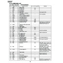
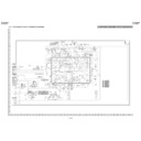
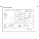
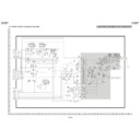
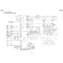
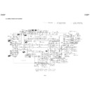
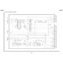
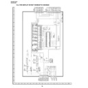
• Block Diagram
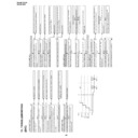
12-12. IC7701 BA5984FP
MOTOR DRIVER
Pin No.
Terminal name
Operation function
Pin No. Terminal name
Operation function
1
LD-FWD
Loading driver FWD input terminal
15
V04(+)
Driver CH4 Negative output
2
SL_IN(+)
CH1 Former stage amplifier nonreverse input terminal
16
V04(-)
Driver CH4 Positive output
3
SL_IN(-)
CH1 Former stage amplifier reverse input terminal
17
V03(+)
Driver CH3 Negative output
4
SLOUT
CH1 Former stage amplifier output terminal
18
V03(-)
Driver CH3 Positive output
5
SP_IN(+)
CH2 Former stage amplifier nonreverse input terminal
19
GND
Ground terminal
6
SP_IN(-)
CH2 Former stage amplifier reverse input terminal
20
BIAS
Bias input terminal
7
SP_OUT
CH2 Former stage amplifier output terminal
21
MUTE
Mute control terminal
8
VCC
Power terminal
22
FO_OUT
CH3 Former stage amplifier output terminal
9
LD(-)
Loading driver Negative output
23
FO_IN(-)
CH3 Former stage amplifier reverse input terminal
10
LD(+)
Loading driver Positive output
24
FO_IN(+)
CH3 Former stage amplifier nonreverse input terminal
11
SPIN(-)
Driver CH2 Negative output
25
TR_OUT
CH4 Former stage amplifier output terminal
12
SPIN(+)
Driver CH2 Positive output
26
TR_IN(-)
CH4 Former stage amplifier reverse input terminal
13
SL(-)
Driver CH1 Negative output
27
TR_IN(+)
CH4 Former stage amplifier nonreverse input terminal
14
SL(+)
Driver CH1 Positive output
28
REV
Loading driver REV input terminal
Note 1: Positive and negative output the driver have polarity with respect to input. (An example: 4 pin terminal voltage
‘HIGH’: 14 pin terminal voltage ‘HIGH’)
79
DV-NC55S/H
DV-NC60H
DV-NC60H
Pin No.
Terminal Name
In/Output
Operation function
1
TRAY ACK(L)
Input
Input terminal of [TRAY ACK] from DVD microcomputer
2
DVD LED(L)
Output
DVD LED control terminal
It outputs [L] and is lit during DVD output.
3
DUB LED(L)
Output
VTR
←
DVD LED control terminal
It outputs [L] and is lit in VTR
←
DVD mode.
4
STANDBY LED(L)
Output
Stand-by LED control terminal
It outputs [L] and is lit during stand-by.
5
TEST
Input
IC test terminal. Fixed to GND.
6
XIN
Input
Radiator connection terminal
7
VSS
–
Digital GND
8
XOUT
Output
Radiator connection terminal
9
VDD
–
Power AT_5V
10
R/C
Input
Remote control signal input
11
RESET
Input
Microcomputer reset signal input
12
NC
–
Unconnected
13
POWER KEY
Input
POWER key input: [L] input while key is ON.
14
OPEN/CLOSE KEY
Input
OPEN/CLOSE key input: [L] input while key is ON.
15
EA
Input
Terminal for IC only. Fixed to power supply.
16
POWER OFF
Output
VTR POWER OFF key control terminal
It outputs [H] when the power is OFF.
17
POWER ON
Output
VTR POWER ON key control terminal
It outputs [H] when the power is ON.
18
TIMER MODE
Input
VTR TIMER mode detection terminal
When [H] is output, the VTR power ON/OFF is not controlled.
19
POWER MODE
Input
VTR POWER mode detection terminal
When [TIMER MODE] = [L], DVD is turned ON when the [POWER MODE] is
activated and turned OFF when it is deactivated.
20
REC MODE
Input
VTR REC mode detection terminal
[VTR
←
DVD] key is disabled at [H] input.
21~31
NC
–
No used
32
P-CON(L)
Output
DVD P-CON control terminal
33
SHORT DET(L)
Input
Short circuit detection terminal for DVD P-CON power supply
After [L] is input for 0.5 seconds, P-CON is switched to OFF.
34
NC
–
Unconnected
35
A_OUT_MUTE(L)
Output
Sound output mute control terminal for VTR/DVD common terminal
36
DVD(H)
Output
Output switching control terminal for VTR/DVD common terminal
37
DUB(H)
Output
Input switching control terminal for VTR input 1
38~40
NC
–
No used
41
PLAY MODE(L)
Input
DVD PLAY mode detection terminal
When [TIMER MODE] = [H] and [PLAY MODE] = [L], DVD is not turned OFF even
if the [POWER MODE] is deactivated.
42
STANDBY REQUEST(L)
Output
Control terminal for POWER OFF request to DVD microcomputer
It keeps outputting the request until [STANDBY ACK] = [L] is input.
43
TRAY REQUEST(L)
Output
Control terminal for TRAY operation request to DVD microcomputer
It keeps outputting the request until [TRAY ACK] = [L] is input.
44
STANDBY ACK(L)
Input
Input terminal for [STANDBY ACK] from DVD microcomputer
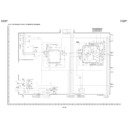
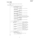
12-13. IC8201 IX1757GE INTERFACE MICOM.
• Terminal description
80
DV-NC55S/H
DV-NC60H
DV-NC60H
Port 2
Port 4
Port 09
Port 3
Port 1
HIGH FREQ
OSC
LOW FREQ
OSC
P22~P20
P47~P40
P17~P10
P37~P30
P07~P00
STOP
INTREQ
TI0, TI1
RXD,
TXD
UART
8bit TMR
SCK,
SI, SO
ch. 0
ch. 1
ch. 1
ch. 0
INTERRUPT
CONTROLLER
STANDBY
CONTROLLER
fs
fc
CLK GEAR, TBT
OSC
SYSCLK
CPU
WDT
ETC0
SERIAL
INTERFACE
EA
EXTERNAL BUS
CONTROLLER
TO0
TO1
RD, WR, ALE, WAIT, CLK
AD0~7
A8~A15
16-bit
Expansion Timer
DVO
ROM
16KB
RAM
512B
RESET
XIN
XOUT
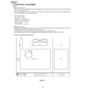
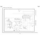
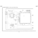
• Block Diagram
81
DV-NC55S/H
DV-NC60H
DV-NC60H
- M E M O -

