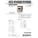
Sony HCD-RV660D / HCD-RV990D Service Manual ▷ View online
29
HCD-RV660D/RV990D
• IC1104 M30620MCN-A28FP (SOUND CONTROL) (MAIN Board (4/4))
Pin No.
Pin Name
I/O
Pin Description
1
S-OUT
O
Serial out signal output
2
S-CLK
O
Serial clock signal output
3
M61530-CLK
O
M61530FP clock signal output
4
SIRCS
I
Sircs signal input
5
M61530-DATA
O
M61530FP data output
6
M61529-DATA
O
M61529FP data output
7
M61529-CLK
O
M61529FP clock signal output
8
EXT.BUS-INPUT
I
External bus input with selector input (Fixed at L)
9
PROCESSOR.MODE-SW
I
Processor mode switch signal input (Fixed at L)
10
SUB.CLOCK-IN
I
Sub clock signal input (32.768 kHz)
11
SUB.CLOCK-OUT
O
Sub clock signal output (32.768 kHz)
12
RESET
I
System reset signal input
13
SYSTEM.CLOCK.OUT
O
System clock signal output (16 MHz)
(16M)
14
VSS
—
Ground
15
SYSTEM.CLOCK.IN (16M)
I
System clock signal input (16 MHz)
16
VCC
—
Power supply pin (+3.3 V)
17
PULL.UP (EVER3.3V)
I
Pull up (EVER +3.3 V)
18
AC-CUT
I
AC cut select signal input (L: ON, H: OFF)
19
VIDEO-OUT-SW
O
Video out switch signal output (L: DVD, H: other)
20
RDS-INT
I
Not used (Connect to VSS)
21
RDS-DATA
I
Not used (Connect to VSS)
22
ST-MUTE
O
Stereo mute select signal output (L: OFF, H: ON)
23
STEREO
I
Stereo select signal input (L: ON, H: OFF)
24
TUNED
I
Tuned select signal input (L: ON, H: OFF)
25
ST-CE
O
Stereo chip enable signal output
26
ST-DOUT
O
Stereo data out signal output
27
ST-DIN
I
Stereo data in signal input
28
ST-CLK
O
Stereo clock signal output
29
IIC-CLK
I/O
IIC clock signal input/output
30
IIC-DATA
I/O
IIC data input/output
31
SYS-POWER
O
System power select signal output (L: OFF, H: ON)
32
SYS-RESET
O
System reset signal output
33
M-REQ
I
DAC mute request select signal input from ZIVA. (L: ON, H: OFF)
34
VIDEO-MUTE1
O
Video mute 1 select signal output (L: ON, H: OFF)
35
VIDEO-MUTE2
O
Video mute 2 select signal output (L: ON, H: OFF)
36
DAC-MUTE
O
Not used (Open)
37
REAR-MUTE
O
Surround (rear) mute select signal output (L: ON, H: OFF)
38
CENTER-MUTE
O
Center mute select signal output (L: ON, H: OFF)
39 to 46
NO-USE
O
Not used (Open)
47
TBL-POS
O
Table motor drive control signal output (+)
48
TBL-NEG
O
Table motor drive control signal output (-)
49
LOD-POS
O
Loading motor drive control signal output (+)
50
LOD-NEG
O
Loading motor drive control signal output (-)
51
ENCODER-SW1
I
Disc tray address signal input (Disc 1)
52
ENCODER-SW2
I
Disc tray address signal input (Disc 2)
53
ENCODER-SW3
I
Disc tray address signal input (Disc 3)
54
EJECT-SW
I
Open/close select signal input (L: open, H: close)
55
T-SENS
I
Table sensor signal input
56
HP-SW
I
Headphones in/out select signal input (L: out, H: in)
57
MIC-SW
I
Microphone in/out select signal input (L: out, H: in)
58
A-TRG
O
Trigger out ON/OFF select signal output (deck A) (L: OFF, H: ON)
30
HCD-RV660D/RV990D
Pin No.
Pin Name
I/O
Pin Description
59
B-TRG
O
Trigger out ON/OFF select signal output (deck B) (L: OFF, H: ON)
60
A-SHUT-IN
I
Reel pulse signal input (deck A)
61
B-SHUT-IN
I
Reel pulse signal input (deck B)
62
VCC
—
Power supply pin (+3.3 V)
63
SWFR-MUTE
O
Sub woofer mute ON/OFF select signal output (L: ON, H: OFF)
64
VSS
—
Ground
65
CAPM-CONT
O
Capstan motor ON/OFF select signal output (L: OFF, H: ON)
66
B-REC.FWD
I
REC (FWD) switch in signal input (deck B) (active L)
67
B-REC.REV
I
REC (REV) switch in signal input (deck B) (active L)
68
A-HALF
I
Half in signal input (deck A) (active L)
69
B-HALF
I
Half in signal input (deck B) (active L)
70
A-PLAY
I
Playback switch in signal input (deck A) (active L)
71
B-PLAY
I
Playback switch in signal input (deck B) (active L)
72
AMS-IN
I
AMS in select signal input (L: without music, H: with music)
73
DISPLAY-KEY
I
Display key signal input (active L)
74
POWER-KEY
I
Power key signal input (active L)
75
M-RESET
O
To other micon’s reset signal output
76
STANDBY-LED
O
Standby LED ON/OFF select signal output (L: ON, H: OFF)
77
BIAS
O
Bias ON/OFF select signal output (L: OFF, H: ON)
78
PB-A/B
O
PB deck A/B select signal output (L: deck B, H: deck A)
79
TC-RELAY
O
Tape REC/PB control signal output (L: REC, H: PB (other))
80
PB-MUTE
O
PB mute select signal output (L: ON, H: OFF)
81
REC-MUTE
O
REC mute select signal output (L: ON, H: OFF)
82
FAN
O
Fan motor ON/OFF control signal output (L: OFF, H: 300 msec)
83
LINEOUT-MUTE
O
MD (VIDEO) mute ON/OFF select signal output (L: ON, H: OFF)
84
LINE-MUTE
O
TA line mute ON/OFF select signal output (L: ON, H: OFF)
85
STK-MUTE
O
STK mute ON/OFF select signal output (L: ON, H: OFF)
86
PROTECT
I
Protect ON/OFF select signal input (L: ON, H: OFF)
87
STB-RELAY
O
Standby relay ON/OFF select signal output (L: OFF, H: ON)
88
FRONT-RELAY
O
Front speaker relay ON/OFF select signal output (L: OFF, H: ON)
89
REAR-RELAY
O
Rear/center/sub woofer speaker relay ON/OFF select signal output (L: OFF, H: ON)
90
NO-USE
O
Not used (Open)
91
VACS-IN1 ILLUMI-IN
I
VACS & Illumi in 1 signal input (A/D)
92
VACS-IN2
I
VACS in 2 signal input (thermal VACS)
93
NO-USE
O
Not used (Open)
94
MODEL-IN
I
Model in signal input (A/D)
95
SPEC-IN
I
Destination in signal input (A/D)
96
AVSS
—
Analog ground
97
I-HOLD
O
Fan motor ON/OFF select signal output (L: OFF, H: ON)
98
V.REF
—
AV reference voltage pin (+3.3 V)
99
AVCC
—
Power supply pin (+3.3 V)
100
S-IN
I
Serial in signal input
31
HCD-RV660D/RV990D
• IC101 µPD780232GC-081-8BT (SYSTEM CONTROL, FL DRIVER) (PANEL Board)
Pin No.
Pin Name
I/O
Pin Description
1
VDD
—
Power supply pin (+5 V)
2
VSS
—
Ground
3
X1
I
System clock signal input (5 MHz)
4
X2
I
System clock signal input (5 MHz)
5
IC
I
Directly connect to ground.
6
RESET
I
Reset signal input (active L)
7
S-CLK
I
Serial clock signal input
8
S-IN
I
Serial in signal input
9
S-OUT
O
Serial out signal output
10 to 15
NC
O
Not used (Open)
16
VOL-A
I
VOLUME encoder in A signal input
17
VOL-B
I
VOLUME encoder in B signal input
18
AVSS
—
Analog ground
19
NC
I
Not used (Connect to ground)
20 to 22
KEY2 to KEY0
—
Key in signal input
23
VSS
—
Ground
24
AVDD
—
Analog power supply pin (+5 V)
25
VDD
—
Power supply pin (+5 V)
26
DVD-LED
O
DVD LED ON/OFF select signal output (L: OFF, H: ON)
27
TUNER-LED
O
TUNER/BAND LED ON/OFF select signal output (L: OFF, H: ON)
28
TAPE-LED
O
TAPE A/B LED ON/OFF select signal output (L: OFF, H: ON)
29
MD-LED
O
MD (VIDEO) LED ON/OFF select signal output (L: OFF, H: ON)
30
GAME-LED
O
GAME LED ON/OFF select signal output (L: OFF, H: ON)
31 to 36
PS1-LED to PS6-LED
O
Power stream LEDs ON/OFF control signal output (L: OFF, H: ON)
37
MULTI-LED
O
MULTI CHANNEL DECODING LED ON/OFF select signal output (L: OFF, H: ON)
38 to 44
NC
O
Not used (Open)
45 to 58
S1 to S14
O
FL segment control signal output (L: OFF, H: ON)
59
VDD
—
Power supply pin (+5 V)
60
V.LOAD
—
V.LOAD
61 to 67
S15 to S21
FL segment control signal output (L: OFF, H: ON)
68 to 80
G1 to G13
FL grid control signal output (L: OFF, H: ON)


