Sharp LC-42XD1E (serv.man6) Service Manual ▷ View online
LC-42XD1E/RU
5 – 21
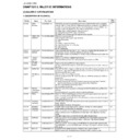
17. IC4404: VHiLCX244FT-1Y
Buffer/Line Driver
18. IC4604: VHiTSH73CPT-1Y
*3-OP-AMP
Pin No.
Pin Name
I/O
Pin Function
1, 19
10E, 20E
I
Output Enable Input 1 and 2
2, 4, 6, 8, 11, 13, 15, 17
1A1-1A4, 2A1-2A4
I
Data Inputs
9, 7, 5, 3, 12, 14, 16, 18
1Y1-1Y4, 2Y1-2Y4
O
Data Outputs
10
GND
—
Ground.
20
VCC
—
Power Source.
Pin No.
Pin Name
I/O
Pin Function
1
STB1
I
Standby Input Terminal1.
2
STB2
I
Standby Input Terminal2.
3
STB3
I
Standby Input Terminal3.
4
VCC —
Power
Source.
5
+IN1
I
Non Inverting Input1.
6
-IN1
I
Invreting Input1.
7
OUT1
O
Output1.
8
OUT2
O
Output2.
9
-IN2
I
Inverting Input2.
10
+IN2
I
Non Inverting Input2.
11
VCC
—
Power Source.
12
+IN3
I
Non Inverting Input3.
13
-IN3
I
Inverting Input3.
14
OUT3
O
Out put3.
LC-42XD1E/RU
5 – 22
19. IC202: RH-iXB682WJZZQ
CDFDM DEMODURATOR
1. All input are 3.3V compatible
2. All bidirectional pads 3.3V capable
3. All output are 3.3V capable.
Pin No.
Pin Name
I/O
Pin Function
12
RESET
I
Hardware reset, active low.
62
XTALI
I
Crystal oscillator input/external clock(1.8V).
63
XTALO
O
Crystal oscillator output.
61
VCCXTAL1.8
—
Analog oscillator supply(1.8V)
64
GNDXTAL
—
Analog oscilltor ground.
2
DVCCA1.8
—
Analog part digital supply(1.8V)
5
REFM
I
Internal negative reference.
6
REFP
I
Internal positive reference.
3
VCCA1.8
—
Analog supply(1.8V).
9
INM
I
Negative analog input.
10
INP
I
Positive analog input.
4,11
GNDA
—
Analog ground.
1
DGNDA
—
Analog ground.
7
VR
I
Reference.
8
VCCA3.3
—
Analog supply (3.3V)
21
SDA
I/O
Serial data (open drain)
20
SCL
I
Serial clock (open drain)
19
SDAT
I/O
SDA tuner (open drain)
18
SCLT
I
25, 26, 27, 29, 31, 32, 33, 34 D7/0
O
Serial D7,MPEG data.
36
CLK_OUT
O
MPEG byte or bit clock.
23
STR_OUT
O
MPEG first byte sync.
38
D/P
O
MPEG data valid/parity.
40
ERROR
O
MPEG packet error.
51
HFECO
O
Hierarchical FEC output bit 0.
50
CCLK/HFC1
O
Hierarchical FEC output bit 1 or clock for constellation display.
49
CDATA/HFC2
O
Hierarchical FEC output bit 2 or data for constellation display.
48
CIQ/HFEC3
O
Hierarchical FEC output bit 3 or IQ validation for constellation display.
16
AGC1
I/O
RF AGC control
14
AGC2
I/O
IF AGC control
17,60
TEST
—
Reserved test mode, must be ground.
58
IP0
I
General-purpose input port0 and ADC input for RF level monitoring
45
OP0
I/O
General-purpose output port0
43
LOCK/OP1
I/O
General-purpose output port1 or lock indicator.
42
LOCK/OP2
O
general-purpose output port2 or lock indicator.
47
AUX_CLK
I/O
Auxiliary clock.
55
CS0
I
Chip select LSB.
53
CS1
I
Chip select MSB.
13, 28, 39, 57
VDD
—
Digital core supply.
22, 35, 44, 52
VDD_3.3
—
Digital IO supply.
15, 24, 30, 37, 41, 46, 54,
56, 59
56, 59
GND
—

