Sharp 76DW-18H (serv.man3) Service Manual ▷ View online
Wide Screen, Colour Television CW100 Chassis
Sharp Electronics (UK) Ltd
Technical Support
February 99
Page 33
The E / W parabola is generated in IC6110, and applied to pin6 of IC501b. (Non inverting input pin).
Pin 5 of IC501b (inverting pin) has a ramp waveform applied to it from the collector of Q501. This
ramp is generated from the horizontal drive signal (also used for vertical output generation).
Pin 5 of IC501b (inverting pin) has a ramp waveform applied to it from the collector of Q501. This
ramp is generated from the horizontal drive signal (also used for vertical output generation).
The application of the input signal (E/W parabola) and a ramp waveform to the op-amp are all that is
required to perform pulse width modulation proportionate to the input signal. Once this has passed
through the switching amplifier, it the output will appear as varying mark - space ratio square wave
with a swing of
required to perform pulse width modulation proportionate to the input signal. Once this has passed
through the switching amplifier, it the output will appear as varying mark - space ratio square wave
with a swing of
±
13V (similar to the vertical stage).
This output is fed via Q605 & Q607. The effect of the East-West circuit is to reduce the amount of
charge available across C610 (Figure 2); thus directly affecting the width of the picture. The fact that
the signal is pulsed rather than analogue will have no effect, the result is the same with an added
advantage of less heat generated by power dissipation in this stage.
charge available across C610 (Figure 2); thus directly affecting the width of the picture. The fact that
the signal is pulsed rather than analogue will have no effect, the result is the same with an added
advantage of less heat generated by power dissipation in this stage.
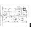
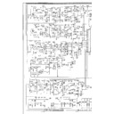
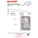
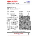
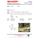
Figure 1 76DW18H East/West Circuit
In addition due to the size of the CRT fitted to the 76DW18H, the East/West drive signal is also fed to
another switching amplifier (IC503) This signal is used to alter the inductance of the line linearity
circuit and also modulate the focus. Ensuring that the linearity and focus is constant across the width
of the CRT.
another switching amplifier (IC503) This signal is used to alter the inductance of the line linearity
circuit and also modulate the focus. Ensuring that the linearity and focus is constant across the width
of the CRT.
Diode Modulator
40V
200V
13V
LOPT pin6
LOPT
ABL
Scan Coils
Line pulses
East/ West Drive
+
-
+
-
Q607
Q605
Q608
Q501
D510
D508
D509
C2V7
C2V7
D623
D624
D618
D617
D616
D612
D625
C12
C12
D626
C12
C12
D628
DF1
C635
C630
C626
T602
R645
C623
R642
R643
R644
R646
R647
IC503A
R545
R546
C509
C521
R537
R567
R566
IC501A
R502
140V
R538
R541
R627
R639
140V
R610
L602
R651
C606
C631
D601
L604
C619
R624
L605
13V
C607
13V
Wide Screen, Colour Television CW100 Chassis
Sharp Electronics (UK) Ltd
Technical Support
February 99
Page 34
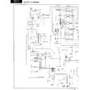
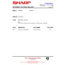
Figure 2 Line Output
+200V
+13V
-13V
+40V
ABL
Screen
Focus 1
Focus 2
DF1
EHT
140V
Scan Coils
East/West Circuit
+8V
-19V
R602
D619 D620
L606
R604
R641
R606
D630
L609
Q601
R605
R601
R603
Q602
Q603
Q604
R634
C603
Line
Drive
Drive
D610 R607
C604
R619
D605
C632 C610
C601 C633
9
4
5
6
1
10
8
13
7
2
3
T601
R648
HPROT
Sharp Electronics (UK) Ltd
Technical Support
February 99
Page 35
SELF ASSESSMENT QUESTION ANSWERS
Section
Question
Answer
Name two conditions that will turn on
Q702?
Q702?
Standby & Over-current
What is the supply voltage to IC1001 during
standby?
standby?
Zero volts
What will be measured with a DVM at the
base of Q702 during over-current?
base of Q702 during over-current?
Zero volts
If Q703 is open circuit, what would happen
to the power supply frequency?
to the power supply frequency?
Power supply will stop oscillating
P
o
w
e
r S
uppl
y
If load increase on the power supply, what
will happen to the frequency?
will happen to the frequency?
Decreases, allowing more energy to
transferred across T701
transferred across T701
What is the default condition of IC6702 pin
15?
15?
Low.
If IC6702 pin 15 is high what will happen to
the Dolby power supply?
the Dolby power supply?
Turn off
Sl
a
v
e
Pro
ce
s
s
o
r
What type of device is IC6702?
Processor with a combine volatile Memory
What is the active level of IC1001 pin 78?
Low. (CTV will switch to standby)
Dat
a
Com
m
u
n
ic
a
ti
on
If the 100Hz PWB reset is permanently
high, what will happen to the line drive?
high, what will happen to the line drive?
Line drive will not start. Reset level is low
During 100Hz scan, what is the frame
frequency?
frequency?
25Hz, the number of fields per frame is
increase from 2 to 4 therefore frame
frequency dose not alter.
increase from 2 to 4 therefore frame
frequency dose not alter.
Why is the line frequency doubled?
Twice the amount of date within the 25Hz
frame to be displayed.
frame to be displayed.
100Hz
P
W
B
What is the difference in the number of
pixels (picture area) per line between NTSC
& PAL?
pixels (picture area) per line between NTSC
& PAL?
No difference, they both have 720 pixels per
line
line

