Sharp XG-C455W (serv.man5) Service Manual ▷ View online
XG-C455W/PG-C355W
5 – 5
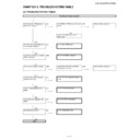
RGB and component signal check
Send component signal or RGB signal of 1080i (or 720P) from
COMPUTER/COMPONENT Terminal.
Select COMPUTER1 or COMPUTER2 using keys on the main
unit or the remote control.
YES
Is image displayed normally?
YES
End
NO
Are picture signals sent to TL2502, TL2507, and TL2508?
NO
Check IC2403 and the peripheral circuits.
YES
Is 3.3V applied to TL1723 and TL1734?
NO
Check IC1703, IC1713 and peripheral circuits.
YES
Is 2.5V applied to TL1733?
NO
Check IC1711 and peripheral circuits.
YES
Check IC2505 and peripheral circuits.
DVI digital input check
Send the DVI digital signal to the DVI Terminal.
Select “DVI-D Computer” using the keys on the main unit or the
remote controller.
Does an image appear properly?
YES
End
NO
Is the DVI signal supplied to R2549, R2550, R2552, R2553,
R2555, R2556, R2557 and R2558?
R2555, R2556, R2557 and R2558?
NO
Check DVI Terminal, L2801, L2802, L2803, L2804, D2801,
D2802 and peripheral circuits.
D2802 and peripheral circuits.
YES
Is 3.3V applied to TL1723 and TL1734?
NO
Check IC1703, IC1713 and peripheral circuits.
YES
Is 2.5V applied to TL1733?
NO
Check IC1711 and peripheral circuits.
YES
Check IC2505 and peripheral circuits.
XG-C455W/PG-C355W
5 – 6
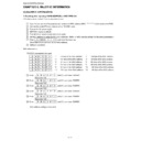
S-VIDEO check
Send S-Video signal (color signal) from S-Video Terminal. Select
S-Video using keys on the main unit or the remote control.
S-Video using keys on the main unit or the remote control.
Is image displayed normally?
YES
End
NO
Is image displayed in black and white?
YES
Check S-VIDEO terminal and peripheral circuits of Q2603 and
SC2701.
SC2701.
NO
Is S-VIDEO signal (Y) sent to TL2606?
NO
Check S-VIDEO terminal and peripheral circuits of Q2601 and
SC2701.
SC2701.
YES
Is 1.8 V applied to TL2613?
NO
Check IC2605 and peripheral circuits.
YES
Is 3.3 V applied to TL1723?
NO
Check IC1703 and peripheral circuits.
YES
Is 3.3 V applied to TL1734?
NO
Check IC1713 and peripheral circuits.
YES
Check IC2602 and peripheral circuits.
VIDEO check
Send VIDEO signal from VIDEO Terminal. Use buttons on the
main unit or the remote control to select VIDEO.
main unit or the remote control to select VIDEO.
Is image displayed normally?
YES
End
NO
Is VIDEO signal sent to TL2605?
NO
Check VIDEO terminal and peripheral circuits of Q2602 and
SC2701.
SC2701.
YES
Is 1.8 V applied to TL2613?
NO
Check IC2605 and peripheral circuits.
YES
Is 3.3 V applied to TL1723?
NO
Check IC1703 and peripheral circuits.
YES
Is 3.3 V applied to TL1734?
NO
Check IC1713 and peripheral circuits.
YES
Check IC2602 and peripheral circuits.
XG-C455W/PG-C355W
5 – 7
Checking the LAN
LAN communication is disabled even though
connecting the control PC with a LAN cable. The
LINK LED (green) does not light up.
connecting the control PC with a LAN cable. The
LINK LED (green) does not light up.
Are the connection of connecting cable and the
settings of IP address, sub-net address and
default gateway correct?
settings of IP address, sub-net address and
default gateway correct?
NO
Check the connecting cable and LAN settings. If the LAN settings are
unknown, contact the network administrator.
If the network settings cannot be saved, replace IC6708 (EEP ROM) as it may
be defective.
unknown, contact the network administrator.
If the network settings cannot be saved, replace IC6708 (EEP ROM) as it may
be defective.
YES
Note: When IC6708 (EEP ROM) is replaced, the MAC address returns to
default. Refer to "Resetting after replacing IC6708 (EEP ROM)" to reset.
default. Refer to "Resetting after replacing IC6708 (EEP ROM)" to reset.
Are the network device (e.g. Hub) between the
control PC and XG-C455W and cable normal?
control PC and XG-C455W and cable normal?
NO
Repair defective parts in the network.
YES
When data is sent from the control PC, do pins
(30) and (31) of IC8201 (PHY receiver) receive
signals?
(30) and (31) of IC8201 (PHY receiver) receive
signals?
NO
Check the peripheral circuit of J8201 (RJ-45 jack with built-in transformer).
YES
Check the PHY receiver IC8201 and the periph-
eral circuits of the microprocessor IC8001.
eral circuits of the microprocessor IC8001.
Display

