Sharp PG-B10S (serv.man15) Service Manual ▷ View online
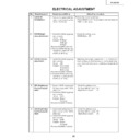
No.
Adjusting point
Adjusting conditions
Adjusting procedure
26
PG-B10S
5
Video Bright-
ness/Contrast
adjustment
ness/Contrast
adjustment
1. Feed an NTSC composite
video 10-step signal (no
setup) with 100% ampli-
tude.
setup) with 100% ampli-
tude.
2. Select the following group
and subjects.
Group : VIDEO
Subject : Bright
Group : VIDEO
Subject : Bright
Contrast
(Process GAMMA interlock)
1. Check the setting value.
Contrast (White Level): 43
Bright (Black Level):
Bright (Black Level):
142
6
PSIG adjust-
ment
ment
1. Select the following group
and subjects.
Group : OUTPUT2
Subject : PSIG-H
Group : OUTPUT2
Subject : PSIG-H
PSIG-L
2. Check the fixed value.
PSIG-H: 140
PSIG-L: 105
PSIG-L: 105
GND
Adjust with PSIG-L
Adjust with PSIG-H
2.0V DC
(typ)
2.0V DC
(typ)
6.8V DC
(typ)
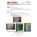
1. Feed the SVGA signal and adjust to make the fol-
lowing PSIG waveform. (TP1201)
7
R/G/B Black
Level Signal
Amplitude
adjustment
Level Signal
Amplitude
adjustment
1. Select the following group
and subjects.
Group : OUTPUT1
Subject :
On Green adjustment
Group : OUTPUT1
Subject :
On Green adjustment
(G1-BLK)
G1-GAIN
G1-GAIN
On Red Adjustment
(R1-BLK)
R1-GAIN
R1-GAIN
On Blue Adjustment
(B1-BLK)
B1-GAIN
B1-GAIN
2. Make sure the process ad-
justment color bags appear
onscreen.
onscreen.
3. Connect a oscilloscope to
pin(2) of P1302 for the G
setting.
setting.
4. Connect the oscilloscope to
pin(1) of P1302 and pin(3)
of P1302 for the R and B
settings, respectively.
of P1302 for the R and B
settings, respectively.
White-to-White
Amplitude
1. Select G1-GAIN. Using the set's control switch or
the remote controller's button, adjust the signal am-
plitude to 4.35 Vp-p ± 0.05 V.
plitude to 4.35 Vp-p ± 0.05 V.
2. Now select G1-BLK. Using the set's control switch
or the remote controller's button, adjust the white-
to-white level to 1.10 Vp-p ± 0.05 V.
to-white level to 1.10 Vp-p ± 0.05 V.
3. Do the same for the R and B settings.
No.
Adjusting point
Adjusting conditions
Adjusting procedure
27
PG-B10S
8
Panel ghost
adjustment
adjustment
1. E N B X R p h a s e a d j u s t m e n t ( R - L C D g h o s t
adjustment)
Increase the setting until the ghost (Note) becomes
visible on the left of the black characters on the R
halftone background.
Decrease the setting by 1 point until the above ghost
disappears.
Lower the setting by another 1 point.
Increase the setting until the ghost (Note) becomes
visible on the left of the black characters on the R
halftone background.
Decrease the setting by 1 point until the above ghost
disappears.
Lower the setting by another 1 point.
2. ENBXG phase adjustment (G-LCD ghost adjustment)
Take the steps as 1 above on the G halftone
background.
background.
3. ENBXB phase adjustment (B-LCD ghost adjustment)
Take the steps as 1 above on the B halftone
background.
Note: Left-hand ghost ÅcA faint duplicate image of
characters or the like seen 12 dots leftward on a
screen
Reference: The above adjustments are needed
because the EPSON panels may have 1- or 2-point
deviation between the LCD lot productions.
background.
Note: Left-hand ghost ÅcA faint duplicate image of
characters or the like seen 12 dots leftward on a
screen
Reference: The above adjustments are needed
because the EPSON panels may have 1- or 2-point
deviation between the LCD lot productions.
1. Get the SVGA60Hz ghost
test pattern on the project
s c r e e n ( t h i c k b l a c k
c h a r a c t e r s o n R G B
halftone background).
Group: OUTPUT3
s c r e e n ( t h i c k b l a c k
c h a r a c t e r s o n R G B
halftone background).
Group: OUTPUT3
2. Sample hold pulse phase
adjustment
M a k e s u r e t h e R C K -
PHASE setting is 282
(initial value).
M a ke s u r e t h e G C K -
PHASE setting is 282
(initial value).
M a k e s u r e t h e B C K -
PHASE setting is 282
(initial value).
M a k e s u r e t h e R C K -
PHASE setting is 282
(initial value).
M a ke s u r e t h e G C K -
PHASE setting is 282
(initial value).
M a k e s u r e t h e B C K -
PHASE setting is 282
(initial value).
3. ENBX width adjustment
Make sure this setting is
the fixed value of 4 (initial
value).
the fixed value of 4 (initial
value).
4. ENBXR phase adjustment
(R-LCD ghost adjustment)
5. ENBXG phase adjustment
(G-LCD ghost adjustment)
6. ENBXB phase adjustment
(B-LCD ghost adjustment)
Make sure these three
settings are all the initial
value of 13.
Make sure these three
settings are all the initial
value of 13.
10
RGB white
balance adjust-
ment
balance adjust-
ment
1. Feed the RGB 50% gray
signal. (SVGA)
2. Select the following group
and subjects.
Group : OUTPUT1
Subject : R1-BLK(R)
Group : OUTPUT1
Subject : R1-BLK(R)
B1-BLK(B)
1. Adjust the R1-BLK and B1-BLK(B) settings so that
the chromaticity based on CL200 becomes as
follows (8500K). x=290±5 y=325±5
follows (8500K). x=290±5 y=325±5
11
sRGB adjust-
ment
ment
1. Feed the RGB 50% gray
signal. (SVGA)
2. Select the following group
and subjects.
Group : OUTPUT1
Group : OUTPUT1
Subject : S-R1-BLK
S-B1-BLK
1. Adjust the R1-BLK and B1-BLK(B) settings so that
the chromaticity based on CL200 becomes as
follows (6500K). x=313±5 y=334±5
follows (6500K). x=313±5 y=334±5
9
RGB
countervoltage
adjustment
countervoltage
adjustment
1. Using the remote controller’s button, adjust the
setting so that the flickering be minimum.
2. Adjust the setting so that the image comes to the
center of the screen.
1. Feed the counter voltage
adjustment signal. (SVGA)
2. Select the following group
and subjects.
Group : OUTPUT3
Subject : RC
Group : OUTPUT3
Subject : RC
GC
BC
BC
No.
Adjusting point
Adjusting conditions
Adjusting procedure
28
PG-B10S
17
DTV Color
saturation
adjustment
saturation
adjustment
1. Select the following group
and subject.
Group
Group
: DTV
Subject : Color
1. Check the fixed value.
Color : 0
18
DVD Tint adjust-
ment
ment
1. Select the following group
and subject.
Group
Group
: DVD
Subject : Tint
1. Check the fixed value.
Tint : 5
19
DVD Color
saturation
adjustment
saturation
adjustment
1. Select the following group
and subject.
Group
Group
: DVD
Subject : Color
1. Check the fixed value.
Color : 0
15
Video
sharpness
adjustment
sharpness
adjustment
1. SGroup: VIDEO
Subject: Sharpness
1. Check the preset value.
Sharpness: 3
16
DTV Tint
adjustment
adjustment
1. Select the following group
and subject.
Group
Group
: DTV
Subject : Tint
1. Check the fixed value.
Tint : 5
13
Video Tint
adjustment
adjustment
1. Select the following group
and subject.
Group
Group
: VIDEO
Subject : Tint
1. Check the fixed value.
Tint : 128
12
Automatic color
irregularity
correction
irregularity
correction
1. Apply the automatic color
correction using the auto-
matic color irregularity cor-
rection system.
matic color irregularity cor-
rection system.
1. Make sure that no remarkable uneven color remains
on the screen.
14
Video Color
saturation
adjustment
saturation
adjustment
1. Select the following group
and subject.
Group
Group
: VIDEO
Subject : Color
1. Check the fixed value.
Color : 135
20
DVD Sharpness
adjustment
adjustment
1. Check the fixed value.
Sharpness :1
1. Select the following group
and subject.
Group
Group
: DVD
Subject : Sharpness
No.
Adjusting point
Adjusting conditions
Adjusting procedure
29
PG-B10S
1. Select OFF from the process mode.
Make sure the off-timer starts with 5 minutes
onscreen and count one minute in one second.
And then indication is 0 minute, the power supply
of the set is cut off.
onscreen and count one minute in one second.
And then indication is 0 minute, the power supply
of the set is cut off.
24
Off-timer per-
formance
formance
1. Heat the thermistor with a
hair dryer.
1. Make sure that the temperature is indicated.
25
Thermistor
performance
checking
performance
checking
1. Make the following settings.
Process adjustment
Remote control adjustment
SS3
Factory setting at 3
27
Delivery set-
tings
tings
1. Feed the phase check pat-
tern signal.
1. In the VGA, SVGA and XGA modes, make sure the
Clock, Phase, H-Pos and V-Pos settings can be au-
tomatically adjusted.
tomatically adjusted.
26
Auto sync
performance
checking
performance
checking
No.
Adjusting point
Adjusting conditions
Adjusting procedure
22
RGB tone
reproduction
adjustment
reproduction
adjustment
1. Make sure the 100% and 95% white as well as the
0% and 5% black gradations are visible.
1. Feed the SMPTE pattern
signal.
23
White balance
checking
checking
1. Use the adjustment condi-
tions in the item 10 for RGB
input and item 11 for sRGB
input.
input and item 11 for sRGB
input.
Check that there is no deviation of white balance with
the monitor.
the monitor.
21
Sample hold
pulse phase
checking
pulse phase
checking
1. Check the fixed value.
GCK-PHASE :282
RCK-PHASE :282
BCK-PHASE :282
RCK-PHASE :282
BCK-PHASE :282
1. Feed the SVGA 75-Hz
black signal.
2. Select the following group
and subjects.
Group : OUTPUT3
Subject : GCK-PHASE
Group : OUTPUT3
Subject : GCK-PHASE
RCK-PHASE
BCK-PHASE
BCK-PHASE
Display

