Sharp PG-B10S (serv.man35) User Manual / Operation Manual ▷ View online
-50
Connecting the Projector to Other Devices
Before Connecting
Note
•
Before connecting, be sure to unplug the power cord of the projector from the AC outlet and turn off the devices
to be connected. After making all connections, turn on the projector and then the other devices.
When connecting a computer, be sure that it is the last device to be turned on after all the connections are made.
to be connected. After making all connections, turn on the projector and then the other devices.
When connecting a computer, be sure that it is the last device to be turned on after all the connections are made.
•
Be sure to read the operation manuals of the devices to be connected before making connections.
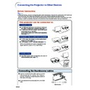
This projector can be connected to:
A computer using:
■ An RGB cable and a ø3.5 mm stereo or mono au-
dio cable (commercially available) (See page
51
.)
■ A DIN-D-sub RS-232C adaptor (AN-A1RS) (sold
separately) and an RS-232C
serial control cable (AN-C10RS) (sold separately)
(See page
serial control cable (AN-C10RS) (sold separately)
(See page
54
.)
Component video or audio-visual equipment:
■ A VCR, Laser disc player or other audio-visual
equipment (See page
52
.)
■ A DVD player or DTV
*
decoder (See page
53
.)
*
DTV is the umbrella term used to describe the new
digital television system in the United States.
A monitor using :
■ Two RGB cables (One is supplied, the other is
sold separately) (See page
55
.)
Connecting the thumbscrew cables
■ Connect the thumbscrew cable making sure that
it fits correctly into the terminal. Then, firmly se-
cure the connectors by tightening the screws on
both sides of the plug.
cure the connectors by tightening the screws on
both sides of the plug.
■ Do not remove ferrite cores attached to the RGB
cable.
Ferrite core
-51
Connections
Connecting the Projector to a Computer
Connecting to a Computer
Using the RGB Cable
Using the RGB Cable
1
Connect the projector to the com-
puter using the supplied RGB cable.
puter using the supplied RGB cable.
•
Secure the connectors by tightening the
thumbscrews.
thumbscrews.
2
To input an audio signal, connect
the projector to the computer using
a ø3.5 mm stereo or mono audio
cable (commercially available or
available as Sharp service part
QCNWGA038WJPZ).
the projector to the computer using
a ø3.5 mm stereo or mono audio
cable (commercially available or
available as Sharp service part
QCNWGA038WJPZ).
Note
•
If the projector does not automatically detect
a RGB signal, the projected image will appear
distorted. To correct, change the menu setting
from “Auto” to “RGB”. The menu setting can
be found in the “Picture” menu. See page
a RGB signal, the projected image will appear
distorted. To correct, change the menu setting
from “Auto” to “RGB”. The menu setting can
be found in the “Picture” menu. See page
38
.
•
See page
70
“Computer Compatibility Chart”
for a list of computer signals compatible with
the projector. Use with computer signals other
than those listed may cause some of the func-
tions to not work.
the projector. Use with computer signals other
than those listed may cause some of the func-
tions to not work.
•
A Macintosh adaptor may be required for use with
some Macintosh computers. Contact your nearest
Sharp Authorized Projector Dealer or Service Center.
some Macintosh computers. Contact your nearest
Sharp Authorized Projector Dealer or Service Center.
•
Depending on the computer you are using,
an image may not be projected unless the sig-
nal output setting of the computer is switched
to the external output. Refer to the computer
operation manual for switching the computer
signal output settings.
an image may not be projected unless the sig-
nal output setting of the computer is switched
to the external output. Refer to the computer
operation manual for switching the computer
signal output settings.
•
When using the ø3.5 mm mono audio cable,
the volume level will be half of when using
the ø3.5 mm stereo audio cable.
the volume level will be half of when using
the ø3.5 mm stereo audio cable.
Supplied
accessory
accessory
RGB cable
Computer
2
ø3.5 mm stereo or mono audio
cable (commercially available or
available as Sharp service part
QCNWGA038WJPZ)
cable (commercially available or
available as Sharp service part
QCNWGA038WJPZ)
1
RGB cable
To RGB output terminal
To audio output terminal
“Plug and Play” function (when connecting to a 15-pin terminal)
■ This projector is compatible with VESA-standard DDC 1/DDC 2B. The projector and a VESA DDC
compatible computer will communicate their setting requirements, allowing for quick and easy setup.
■ Before using the “Plug and Play” function, be sure to turn on the projector first and the connected
computer last.
Note
•
The DDC “Plug and Play” function of this projector operates only when used in conjunction with a VESA
DDC compatible computer.
DDC compatible computer.
-52
Connecting the Projector to Other Devices
Connecting to Video Equipment
Connecting to Video
Equipment Using an
S-video, a Composite
Video or an Audio Cable
Equipment Using an
S-video, a Composite
Video or an Audio Cable
Using an S-video, video, or audio cable, a VCR,
laser disc player or other audio-visual equip-
ment can be connected to INPUT 2, INPUT 3
and AUDIO input terminals.
laser disc player or other audio-visual equip-
ment can be connected to INPUT 2, INPUT 3
and AUDIO input terminals.
1
Connect the projector to the
video equipment using an S-
video cable or a composite video
cable (both commercially avail-
able).
video equipment using an S-
video cable or a composite video
cable (both commercially avail-
able).
2
Connect the projector to the
video equipment using a ø3.5
mm minijack to RCA audio cable
(commercially available).
video equipment using a ø3.5
mm minijack to RCA audio cable
(commercially available).
Note
•
The INPUT 2 (S-VIDEO) terminal uses a video
signal system in which the picture is sepa-
rated into color and luminance signals to re-
alize a higher-quality image. To view a higher-
quality image, use a commercially available
S-video cable to connect the INPUT 2 termi-
nal on the projector and the S-video output
terminal on the video equipment.
•
A ø3.5 mm minijack to RCA audio cable (com-
mercially available) is required for audio input.
mercially available) is required for audio input.
To S-video output terminal
To video output terminal
To audio output terminal
VCR or other audio-visual equipment
1
S-video cable
(commercially available)
(commercially available)
1
Composite video cable
(commercially available)
(commercially available)
2
ø3.5 mm minijack to RCA audio cable
(commercially available)
(commercially available)
-53
Connections
Optional
cable
cable
3RCA to 15-pin D-sub cable
AN-C3CP
(9'10" (3.0 m))
AN-C3CP
(9'10" (3.0 m))
To analog component output terminal
To audio output terminal
DVD player or
DTV
DTV
*
decoder
Connecting to Component
Video Equipment
Video Equipment
Use a 3 RCA to 15-pin D-sub cable when con-
necting to the INPUT 1 terminal, component
video equipment such as DVD players and
DTV* decoders.
necting to the INPUT 1 terminal, component
video equipment such as DVD players and
DTV* decoders.
*
DTV is the umbrella term used to describe the
new digital television system in the United
States.
States.
1
Connect the projector to the
video equipment using the 3
RCA to 15-pin D-sub cable.
video equipment using the 3
RCA to 15-pin D-sub cable.
•
Secure the connectors by tightening the
thumbscrews.
thumbscrews.
2
Connect the projector to the
video equipment using a ø3.5
mm minijack to RCA audio cable
(commercially available).
video equipment using a ø3.5
mm minijack to RCA audio cable
(commercially available).
Note
•
If the projector does not automatically de-
tect a COMPONENT signal, the projected
image will appear distorted. To correct,
change the menu setting from “Auto” to
“Component”. The menu setting can be
found in the “Picture” menu. See page
tect a COMPONENT signal, the projected
image will appear distorted. To correct,
change the menu setting from “Auto” to
“Component”. The menu setting can be
found in the “Picture” menu. See page
38
.
•
A ø3.5 mm minijack to RCA audio cable
(commercially available) is required for au-
dio input.
(commercially available) is required for au-
dio input.
1
3 RCA to 15-pin D-sub cable
(sold separately)
(sold separately)
2
ø3.5 mm minijack to RCA audio cable
(commercially available)
(commercially available)

