Sharp MX-M850 (serv.man19) Service Manual ▷ View online
MX-M1100 IMAGE PROCESS SECTION H – 9
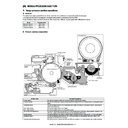
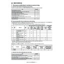
F. Process control execution conditions and timing
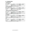
The process control is executed under the following conditions at the following timing.
(*1) : Setting of the process control execution conditions and timing with SIM 44-28.
The execution conditions and timing of each process control can be set with SIM 44-28.
The execution conditions and timing of each process control can be set with SIM 44-28.
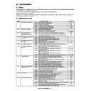
G. Process control conditions and settings
No.
Item
Forcible execution
by the simulation
Execution conditions, timing
1
Image density sensor sensitivity
adjustment
adjustment
TC44-2
Before execution of the high density image correction (High density process control)
2
OPC drum dark potential correction
TC44-3
Before execution of the high density image correction (High density process control)
3
OPC drum photo sensitivity
correction/OPC drum charging
correction
correction/OPC drum charging
correction
Before execution of the high density image correction (High density process control)
4
High density image correction (High
density process control)
density process control)
TC44-6
(TC44-2/44-3)
(TC44-2/44-3)
Depends on the set conditions of SIM 44-28. (*1)
5
Half-tone density correction (half-tone
process control)
process control)
TC-44-34
After execution of the high density image correction (High density process control)
6
Toner density correction
When there is a change in the temperature/humidity. When the developer counter
reaches the specified value. When the developing bias voltage changes more than the
specified level after execution of the high density image correction (high density
process control).
reaches the specified value. When the developing bias voltage changes more than the
specified level after execution of the high density image correction (high density
process control).
7
Transfer current correction
When the paper type or the paper size is changed. When there is a change in the
temperature/humidity.
temperature/humidity.
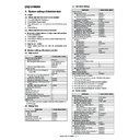
Item
Process control execution conditions
Setting
(Disable / Enable)
Default
SW ON
In previous rotation when turning on the power (canceling the sleep mode).
Disable / Enable
0 (Enable)
24H
When the machine has been left in READT (sleep setting) mode for 24 hours or more.
Disable / Enable
0 (Enable)
HUM
When a change in the temperature/humidity greater than that in execution of the previous
process control is found by monitoring the temperature/humidity at the specified time
interval (180 min).
process control is found by monitoring the temperature/humidity at the specified time
interval (180 min).
Disable / Enable
0 (Enable)
REV1
When the developing roller rotation time passes the specified level (10 min) after turning
on the power.
on the power.
Disable / Enable
0 (Enable)
REV2
When the developing rotation time reaches the specified level (30 min) from execution of
the previous density correction.
the previous density correction.
Disable / Enable
0 (Enable)
INITIAL
When warming up after clearing the counters of the OPC drum and the developing unit.
Disable / Enable
0 (Enable)
PIX
When the toner (pixel) count value accumulated from execution of the previous high
density correction exceeds the specified level.
density correction exceeds the specified level.
Disable / Enable
1 (Disable)
HUM HOUR
Setting of the temperature/humidity monitor time interval (min) in the item of HUM.
1-255
180
HUM_DIF
Specified value of the area difference in the item of HUM compared with that in execution
of the previous process control
of the previous process control
1-16
2
REV1_MINUTE
Developing rotation time (min) of the item of REV1 after turning on the power
1-255
10
REV2_MINUTE
Developing rotation time(min) of the item of REV2 after execution of the previous density
correction
correction
1-255
30
PIX_RATIO
Magnification ratio of the accumulated toner count value of the item of PIX from execution
of the previous high density correction
of the previous high density correction
1-99
10
PATCH
After passing the specified time of rotation of the developing roller from the previous high
density process control, and when the toner patch image is made and the difference
between its density and the target density level is greater than the value specified with the
PATCH CONTROL.
density process control, and when the toner patch image is made and the difference
between its density and the target density level is greater than the value specified with the
PATCH CONTROL.
Disable / Enable
1 (Disable)
PATCH MINUTE
Operation interval of item PATCH.
1-255
10
PATCH RATIO
Specified value of the difference between the toner patch image and the target density
level in the operation of item PATCH.
level in the operation of item PATCH.
1-100
100
MX-M1100 IMAGE PROCESS SECTION H – 10
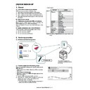
H. Process control operation flow
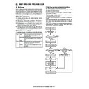
The process control is executed in the following flow.
Along with execution of the OPC drum dark potential correction, the high density image correction (high density process control), and the half-
tone density correction (half-tone process control), the developing bias voltage, the main charger grid voltage, and the laser power are cor-
rected and changed in the following flow.
The developing bias voltage, the main charger grid voltage, and the laser power are finally determined with Job No. 6B, 8B, and 9B.
Job
No.
Job
No.
1
OPC drum dark potential correction
(DVB + Cleaning filed)
(DVB + Cleaning filed)
Vg/Vo
2A
DVB
3
EDV
Effective developing bias voltage check
4A
EDV
Effective developing bias voltage securing
5A
150V
6A
LDP
Half-tone density correction (Half-tone process control)
7
EDV
Effective developing bias voltage check
8A
EDV
Effective developing bias voltage securing
9A
150V
Proper cleaning field securing
4B
DVB
Developing bias voltage change
5B
Vg/Vo
OPC drum dark potential correction
2B
VL
OPC drum dark potential detection
8B
DVB
Developing bias voltage change
9B
Vg/Vo
OPC drum dark potential correction
6B
HVL/VL
High density image correction (High density process
control) (Developing bias voltage correction)
control) (Developing bias voltage correction)
Laser power change/ OPC drum light potential
change (OPC drum light potential VL detection)
change (OPC drum light potential VL detection)
Proper cleaning field securing (keep the diffrence in
potential between DV bias and Drum serface.)
potential between DV bias and Drum serface.)
: Main charger grid voltage
: OPC drum dark potential
: Developing bias voltage
: Effective developing bias voltage (DVB - VL)
: Vo - DVB
: Half-tone potential
: Light potential
: Laser power
Vg
Vo
DVB
EDV
Cleaning filed
HVL
VL
LDP

