Sharp AR-PB8 (serv.man6) Service Manual ▷ View online
17)Install the rear cabinet of the copier.
•
Remove the seven screws and remove the rear cabinet.
18)Remove the shield plate of the copier.
•
Remove the five screws and remove the shield plate.
19)Cut off the jumper wire (JP5).
•
Use nippers to cut off the jumper wire (JP5) which is attached
to the PWB as shown below. Be careful not to drop the jumper
wire in the machine.
to the PWB as shown below. Be careful not to drop the jumper
wire in the machine.
20)Install the shield plate.
•
Install the shield plate with the eight screws.
21)Install the rear cabinet.
•
Install the rear cabinet to the seven screws.
22)Connect the power plug to the power outlet, and turn on the main
switch which is on the left side of the copier.
23)Check the operation of the job separator.
•
Execute SIM 3-4 with the key operations on the copier.
•
The separator tray moves up and down, and stops after com-
pletion of the simulation.
pletion of the simulation.
•
Press the key to terminate the simulation.
[5] OPERATIONAL DESCRIPTION
•
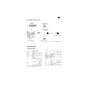
Copy paper exit: The intermediate paper exit tray is pulled up
by the separator motor and the copy paper is discharged to the
lower side of the tray.
by the separator motor and the copy paper is discharged to the
lower side of the tray.
•
Printer/FAX paper exit: The intermediate paper exit tray is
pulled down by the separator motor and the copy paper is
discharged to the upper side of the tray.
pulled down by the separator motor and the copy paper is
discharged to the upper side of the tray.
When paper exit full is detected, the intermediate paper exit tray is
stopped at the upper side.
stopped at the upper side.
To cancel paper exit dull detection, remove the paper exit tray, and
press the start key again.
press the start key again.
Separator tray
Copying
Printer/FAX output
AR-TR2
1 – 4
[6] SIMULATIONS
Main
code
code
Sub
code
Contents
Details of operation
Initial
value
value
Set range
3
2
Shifter job separator
sensor operation check
sensor operation check
Used to check the sensors state in the shifter job separator with the LED
on the operation panel.
on the operation panel.
Display
<Lighting at sensor ON>
Shifter HP sensor: Machine position JAM LED
Job separator HP sensor: SPF JAM LED
Paper exit full sensor: Second cassette position JAM LED
3
Shifter operation check
Used to drive the shifter motor at the speed of printing of A4 (8-1/2
×
11"). Pressing the start key or the clear all key moves the shifter to the
home position.
home position.
Key operation
The shifter is moved to the home position: Start key or clear all key
4
Job separator operation
check
check
Used to drive the job separator one way. Pressing the clear key stops
the job separator at the home position.
the job separator at the home position.
Key operation
Stops at the home position: Clear all key
[7] TROUBLE CODES
Main code
Sub code
Detail of trouble
L4
10
Content
Job separator motor abnormality
Detail
●
It does not reach the home position even after about 2.5 sec from starting driving the job separator.
●
The home position is not detected even after about 2.5 sec from rising of the separator tray.
Cause
Home position sensor defect
MCU PWB defect
Separator motor defect
Check and
remedy
Check the operation with SIM 3-2/3-4/3-10.
Cancel the trouble code with SIM 14.
AR-TR2
6 – 1
Printed in Japan.
SHARP CORPORATION
Printing & Reprographic Systems Group
Quality & Reliability Control Center
Yamatokoriyama, Nara 639-1186, Japan
Printing & Reprographic Systems Group
Quality & Reliability Control Center
Yamatokoriyama, Nara 639-1186, Japan
1999 February Printed in Japan
N
AR-TR2
Printed in Japan.
SHARP CORPORATION
Printing & Reprographic Systems Group
Quality & Reliability Control Center
Yamatokoriyama, Nara 639-1186, Japan
Printing & Reprographic Systems Group
Quality & Reliability Control Center
Yamatokoriyama, Nara 639-1186, Japan
1999 February Printed in Japan
N
AR-TR2
Display

