Sharp AM-300 (serv.man7) Service Manual ▷ View online
AM-300DE
3 – 21
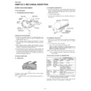
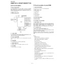
4. Flatbed cover/Scanner unit/Flatbed upper/Drive unit/Flatbed lower
Fig.4
Parts list (Fig. 4)
NOTE: For disassembly of the inside of the unit,
refer to the exploded view in the parts
guide.
guide.
No.
Part name
Qty
No.
Part name
Qty
1
Flatbed cover
1
2
Scanner unit
1
3
Screw (3x12)
1
4
Screw (3x10)
4
5
Hook
6
6
Flatbed upper
1
7
Hook
1
8
Screw (3x6)
1
10
Earth spring 1
1
11
Screw (3x10)
1
12
Drive unit
1
9
Earth spring
1
Mark point the drive unit
Mark point hold lever
Position assembly mark
point same line.
point same line.
IMPORTANT!
Push
Flatbed lower
Push
Must push
this point
when ass'y
Drive unit.
this point
when ass'y
Drive unit.
Drive unit
2
Scanner unit
Screwdriver
Drive
unit
Stopper
plate
4
4
3
4
11
12
8
5
5
5
5
5
5
9
10
7
13
6
4
1 Flatbed cover
Flatbed upper
Flatbed
lower
Drive unit
13
Flatbed lower
1
Drive Unit
Pin exist
upper End
upper End
Hold lever touch
the bottom of
Flatbed lower.
the bottom of
Flatbed lower.
When mounting the drive unit, the hold lever and
the teeth of the system gear must be aligned.
the teeth of the system gear must be aligned.
Hold lever
Hold lever
b
a
Drive unit
Flatbed lower
Hook
12
13
7
Caution
AM-300DE
3 – 22
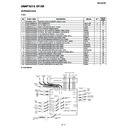
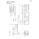
5. Right cover/Front cover/Paper exit unit/Optical unit(LSU)/Fusing unit
Fig.5
Parts list (Fig. 5)
NOTE: For disassembly of the inside of the unit,
refer to the exploded view in the parts
guide.
guide.
No.
Part name
Qty
No.
Part name
Qty
1
Mechanism unit
1
2
Right cover pivot
1
3
Right cover
1
4
Screw (3x10)
1
5
Front cover
1
6
Screw (3x14)
4
8
Screw (3x10)
4
9
Screw (3x8)
1
11
Connector
2
12
Optical unit (LSU)
1
13
Screw
2
10
Earth cable
1
7
4
6
6
8
8
11
11
12 Optical unit (LSU)
Since the parts of this Optical
unit (LSU) cannot be supplied,
change it as a unit.
unit (LSU) cannot be supplied,
change it as a unit.
Fusing unit
Right cover
2
3
Front cover
5
13
13
14
9
10
1
Mechanism unit
7
Paper exit unit
1
14
Fusing unit
1
Paper exit
unit
AM-300DE
3 – 23
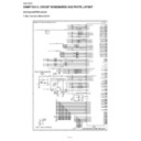
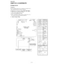
6. Wire treatment
Fig.6
Parts list (Fig. 6)
1
Band (100mm)
6
2
Screw
1
3
Wire holder
1
4
Core (F2154)
1
5
Screw (3x8)
1
6
Core (F2146)
1
No.
Part name
Qty
The AC cord earth cable
pass to the core 2 times.
pass to the core 2 times.
1
3
2
1
4
1
1
CNSCM
CNPN
CNLSR
CNCIS
CNRTH
CNPM
CNPUM
CNFM
CNFM
CNTCT
CNROLSNS
CNTCVR
CNROLSNS
CNTCVR
CNPW
CNHV
CNMM
CNBYPE
CN6
CNPIN
CN2
CNHT
CNPOUT1
CNPOUT2
CNFRT
CNORG
CNHPS
CNSP
CNHPS
CNSP
Control
PWB
PWB
High voltage
PWB unit
PWB unit
AC cord
Power supply PWB unit
7
Core (F2147)
1
6
1
LSU
Earth cable
Earth cable
The CNLSR cable pass
to the core 2 times.
to the core 2 times.
5
The LSU earth cable
pass to the core 1 time.
pass to the core 1 time.
7
1

