Sharp AM-300 (serv.man7) Service Manual ▷ View online
AM-300DE
3 – 1
AM-300DE
Service Manual
CHAPTER 3.
MECHANICAL DESCRIPTION
[1] Mechanical description
1. Facsimile block
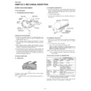
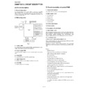
1.1. Document feed block and diagram
2. Document feed operation
is on) is fed with the let out roller and paper feed roller which rotate
together with the pulse motor.
together with the pulse motor.
2) When a specified number of pulses are received from the docu-
3) When a specified number of pulses are received from the docu-
3. Hopper mechanism
3.1. General view
ument.
1) Use of the paper feed roller and separation rubber plate ensures
2) Document separation system:
Separation rubber plate/speed reduction ratio/roller backlash sepa-
ration system
ration system
and free from creases, folds, curls, wet glue, wet ink, clips, staples
and pins.
and pins.
hopper. The first page under the stack will be taken up by the
feed roller to get ready for transmission.
feed roller to get ready for transmission.
nesses together.
3.4. Documents applicable for automatic feed
recording paper should be inserted manually.
Documents heavier than 80g/m
2
in terms of the paper weight must be
duplicated on a copier to make it operative in the facsimile.
Fig. 1
Fig. 2
Document
Document
Front sensor
Separation
rubber plate
rubber plate
Exit pinch roller
Exit roller
CIS
ORG sensor
Transfer
pinch roller
pinch roller
Transfer
roller
roller
Separate
spring
spring
Feed roller
Rear
plate
plate
Fig. 3
Product specifications
Indication
Lower Limit
Upper Limit
Weight
indication
indication
Metric system
indication
indication
52g/m
2
80g/m
2
Thickness
indication
indication
Metric system
indication
indication
0.06mm
0.1mm
Document
size
size
Document size
Range
Range
Minimum (148mm x 182mm)
A4 (210mm x 297mm)
Letter (216mm x 279mm)
Legal (216mm x 356mm)
A4 (210mm x 297mm)
Letter (216mm x 279mm)
Legal (216mm x 356mm)
Number of
ADF sheets
ADF sheets
Document size
Weight
Weight
Minimum ~ Letter/A4 size 20sheets
Legal 1 sheet
Legal 1 sheet
Paper
quality
quality
Kind
Paper of fine quality/bond paper/
Kent paper
Kent paper
Separation
rubber plate
rubber plate
Separation plate
Separate
spring
spring
Feed roller
AM-300DE
3 – 2
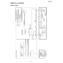
4. Paper path
5. Components layout
CIS
Document input
Envelope
Document exit
Fusing unit
Optical unit (LSU)
Drum cartridge
Toner cartridge
Paper(250 sheets)
Print exit
Fig. 4
4
1
8
2
11
9
10
7
6
3
5
12
13
Fig. 5
No.
PARTS NAME
No.
PARTS NAME
1
Feed roller
8
Drum cartridge
2
Transfer roller
9
Optical unit (LSU)
3
Transfer pinch roller
10
Fusing unit
4
CIS
11
Document feeder tray
5
Output tray
12
Exit roller
6
PU roller assay
13
Exit pinch roller
7
Toner cartridge
AM-300DE
3 – 3
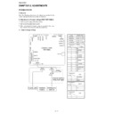
6. Switch/Sensor layout
9
2
10
8
7
11
14
12
13
3
4
5
6
1
Fig. 6
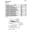
No.
PARTS NAME
TYPE
DESCRIPTION
1
Front sensor
Microcircuit
When the document is set up in the hopper, the front sensor is on.
2
ORG sensor
Microcircuit
When the ORG sensor is on, the document is fed and scanning will be
started.
started.
3
P-IN sensor
Microcircuit
When this switch is turned on, paper transport.
4
Bypass PE sensor
Microcircuit
When this switch is turned on, paper transport.
5
Inter lock switch
Microcircuit
Detects the opening or closing of the Right Cover.
6
PO2 sensor
Microcircuit
Detects when the paper is fed out.
7
Roller switch
Microcircuit
Detects when the Pickup Roller is home position.
8
Toner sensor
Microcircuit
Detects when the Toner Cartridge is set.
9
Home position sensor
Microcircuit
Detects when CIS is ADF scanning position.
10
Tray cover sensor
Microcircuit
Detects when the Paper Tray is set up.
11
PO1 sensor
Photo transistor
Detects when the paper is fed out.
12
Temperature fuse 216
°C
Thermal fuse
When the heat roller temperature rises abnormally, this fuse cuts off the
power relay power line (+24 V line).
power relay power line (+24 V line).
13
Temperature fuse 152
°C
Thermal fuse
When the heat roller temperature rises abnormally, this fuse cuts off the
heater lamp power line.
heater lamp power line.
14
Thermistor
Thermistor
Detects the temperature on the heat roller.
AM-300DE
3 – 4
7. Scanner drive block and diagram
7.1. Overall layout
7.2. Gear layout
Drive switching unit
A
Pin
System gear
Gear
Hold lever
Hold rib
Scanner unit
Home position sensor
Lever
(drive source)
Motor gear
Scan unit drive side gear train
Sheet scan drive side gear train
Drive belt
Scan unit locking lever
System gear
Planet gear A
Planet gear B
System gear biasing spring

