Sharp AL-840 (serv.man8) Service Manual ▷ View online
S008/P001
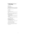
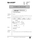
Gear
(1)
Remove the rear cabinet S001/P001 .
(2)
Remove the front upper cabinet S001/P002 .
(3)
Remove the right cabinet S001/P003 .
(4)
Remove the fan motor unit S010/P001 .
(5)
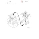
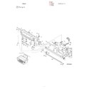
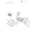
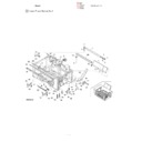
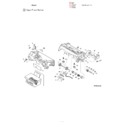
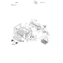
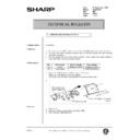
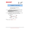
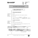
Remove the gear (S008/P001) as shown below.
*
Grease up
When gears are disassembled or replaced, be sure to grease
again.
again.
*
Troubles caused by improper work
1) Noise generation
2) Image deflection
3) Banding
S008/P002
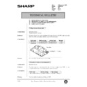
Main motor
(1)
Remove the rear cabinet S001/P001 .
(2)
Remove the front upper cabinet S001/P002 .
(3)
Remove the right cabinet S001/P003 .
(4)
Remove the left cabinet S001/P004 .
(5)
Remove the document table glass S001/P007 .
(6)
Remove the fan motor unit S010/P001 .
(7)
Remove the MCU (PCU) PWB unit S009/Ua002 .
(9)
Remove the gear (S008/P001).
(10) Remove the screw and the connector, and remove the main
motor (S008/P002).
*
Grease up
When gears are disassembled or replaced, be sure to grease
again.
again.
*
Troubles caused by improper work
1) Noise generation
2) Image deflection
3) Banding
S008/P001/GRE
S008/P001/
GRE
S008/P001/GRE
S008/P002
S008/P001/GRE
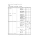
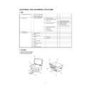
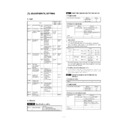
S009
Electrical section
Section
Unit
Part
JOB
CODE
After-work
NOTE
S No.
Part name
Ua No.
Unit name
Ub No.
Unit name
P No.
Part name
JOB No.
S 009
Electrical
Ua 001
Power source,
PWB unit
PWB unit
ASS
P 001
Power switch
ASS
P 002
Fuse
ASS
Ua 002
MCU (PCU) PWB
unit
unit
ASS
SET M1/M2
ADJ M1/
M4
∼
6
Adjustment
is required
when replace
is required
when replace
Ua 003
ICU
PWB/Interface
PWB unit
PWB/Interface
PWB unit
ASS
Ua 004
High voltage/motor
drive PWB unit
drive PWB unit
ASS
9 – 29
S009/Ua001
S009/Ua003
S009/Ua004
S009/Ua002
S009/Ua001/P001
S009/Ua001/P002
S009/Ua001
Power PWB unit
S009/Ua001/P001
Electrical switch
S009/Ua001/P002
Fuse
(1) Remove the rear cabinet S001/P001 .
(2) Remove the front upper cabinet S001/P002 .
(3) Remove the left cabinet S001/P004 .
(4) Remove the screw and the connector.
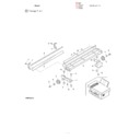
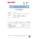
(5) Push the power PWB unit (S009/Ua001) from the inside to
remove.
S009/Ua001
9 – 30
(6) Remove the screw, and remove the power PWB unit (S009/
Ua001) from the base plate.
(7) Remove the power switch (S009/Ua001/P001) and the fuse
(S009/Ua001/P002) from the power PWB unit.
*
After-work
1) Output voltage adjustment (When any part i the power unit is
replaced.)
*
Troubles caused by improper work
1) Power abnormality
S009/Ua002
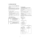
MCU (PCU) PWB unit
(1) Remove the rear cabinet S001/P001 .
(2) Remove the front upper cabinet S001/P002 .
(3) Remove the right cabinet S001/P003 .
(4) Remove the fan motor unit S010/P001 .
(5) Remove the screw and the connector.
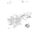
(6) Remove the connector, and push the MCU (PCU) PWB unit
(S009/Ua002) inside then remove.
*
Troubles caused by improper work
1) Machine malfunction
S009/Ua003
ICU PWB interface PWB unit
S009/Ua004
High voltage/motor drive PWB unit
(1) Remove the base bottom base plate S001/P008 .
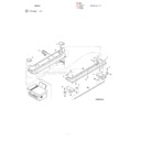
(2) Remove the screw and the connector, and remove the ICU PWB
interface PWB unit (S009/Ua003) and the high voltage/motor drive
PWB unit (S009/Ua004).
PWB unit (S009/Ua004).
S009/Ua001
S009/Ua001/P001
S009/Ua001/
P002
P002
S009/Ua002
9 – 31
*
Troubles caused by improper work
1) Printer malfunction
2) Print defect
S009/Ua003
S009/Ua004
S010
Other section
Section
Unit
Part
JOB
CODE
After-work
NOTE
S No.
Part name
Ua No.
Unit name
Ub No.
Unit name
P No.
Part name
JOB No.
S 010
Others
P 001
Fan motor
ASS
S010/P001
Fan motor
(1) Remove the rear cabinet S001/P001 .
(2) Remove the front upper cabinet S001/P002 .
(3) Remove the right cabinet S001/P003 .
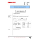
(4) Remove the screw and he connector, and remove the fan motor
unit.
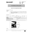
(5) Remove the screw, and remove the fan motor (S010/P001).
*
Troubles caused by improper work
1) Image distortion
S010/P001
9 – 32

