Sharp AL-840 (serv.man8) Service Manual ▷ View online
[9] DISASSEMBLY, ASSEMBLY, MAINTENANCE
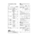
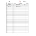
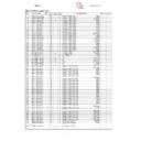
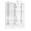
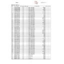
1. List
•
OIL/GRE (Lubricate, grease up) CLN (Clean) ADJ (Adjust) REP (Replace, install)
CHP (Change position); (Clean, replace, lubricate, grease up according to necessity.) ASS (Assemble, disassemble)
CHP (Change position); (Clean, replace, lubricate, grease up according to necessity.) ASS (Assemble, disassemble)
Section
Unit
Part
JOB
CODE
After-work
NOTE
S No.
Part name
Ua No.
Unit name
Ub No.
Unit name
P No.
Part name
JOB No.
S 001
External view
(Cabinet/Cover)
(Cabinet/Cover)
P 001
Rear cabinet
ASS
P 002
Front upper cabinet
ASS
P 003
Right cabinet
ASS
P 004
Left cabinet
ASS
CLN
P 005
Front right lower cabinet
ASS
P 006
Front left lower cabinet
ASS
P 007
Document table glass
ASS
CLN
P 008
Bottom base plate
ASS
P 009
Paper reception tray
ASS
S 002
Operation
Ua 001
Operation unit
ASS
P 001
Hinge
ASS
P 002
Operation control PWB
ASS
P 003
Key top
ASS
S 003
Paper feed, paper
transport
transport
P 001
Paper width detector
ASS
P 002
Paper set lever
ASS
P 003
Paper pressure plate
ASS
P 004
Paper feed roller clutch spring
ASS
GRE
P 005
Paper feed roller
ASS
CLN
P 006
Paper feed clutch sleeve A
ASS
GRE
P 007
Paper feed clutch sleeve B
ASS
GRE
P 008
Paper feed clutch lever
ASS
P 009
Paper separator
ASS
CLN
S 004
Scanner (reading)
Ua 001
Scanner (reading)
unit
unit
ASS
ADJ M3
P 001
Scanner home position sensor
ASS
P 002
Scanner (copy) lamp drive
PWB
PWB
ASS
ADJ M10
Adjustment
is required
when replace
is required
when replace
P 003
Scanner motor
ASS
P 004
Scanner motor gear
GRE
P 005
CCD unit (CCD/lens)
ASS
ADJ M4
CLN
P 006
Scanner rail
GRE
P 007
Scanner shaft
ASS
GRE
P 008
Scanner drive wire
ASS
ADJ M2/M3
Ub 001
Scanner unit
A
A
ASS
ADJ M3
P 001
Scanner (copy) lamp
ASS
ADJ M10
Adjustment
is required
when replace
is required
when replace
CLN
P 002
No. 1 mirror
ASS
CLN
P 003
Scanner lamp light quantity
sensor
sensor
CLN
Ub 002
Scanner unit
B
B
ASS
P 001
No. 2 mirror
ASS
CLN
P 002
No. 3 mirror
ASS
CLN
S 005
Scanner (writing)
Ua 001
Scanner (writing)
unit
unit
ASS
P 001
No. 1 mirror
CLN
P 002
No. 3 mirror
CLN
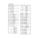
9 – 1
Section
Unit
Part
JOB
CODE
After-work
NOTE
S No.
Part name
Ua No.
Unit name
Ub No.
Unit name
P No.
Part name
JOB No.
S 005
Scanner (writing)
Ua 001
Scanner (writing)
unit
unit
P 003
No. 2 cylindrical lens
CLN
P 004
f
θ
mirror (No. 2 mirror)
ASS
CLN
P 005
Scanning mirror (motor) unit
ASS
CLN
P 006
Laser unit
ASS
P 007
Laser beam sensor
ASS
CLN
P 008
Paper feed solenoid
ASS
P 009
Paper empty detector
ASS
P 010
No. 1 cylindrical lens
CLN
P 011
Toner empty sensor
ASS
S 006
Image process
P 001
Toner cartridge
ASS
P 002
Photoconductor cartridge
ASS
P 003
Developing bias electrode
ASS
CLN
P 004
Photoconductor earth electrode
ASS
CLN
P 005
Transfer roller
ASS
CLN
P 006
Transfer charger electrode
ASS
CLN
P 007
Developing bias electrode
spring
spring
ASS
CLN
P 008
Separation electrode
ASS
CLN
P 009
Main charger electrode SP
ASS
CLN
P 010
Earth electrode SP
ASS
CLN
S 007
Fusing, paper exit
Ua 001
Fusing unit
ASS
P 001
Pressure roller
ASS
CLN
P 002
Paper guide sheet
ASS
CLN
P 003
Paper exit roller L
ASS
CLN
P 004
Paper exit roller U
ASS
CLN
P 005
Paper exit detector
ASS
P 006
Fusing temperature sensor
ASS
CLN
P 007
Heat roller
ASS
CLN
P 008
Heater lamp
ASS
P 009
Separation pawl
ASS
CLN
P 010
Temperature fuse A
ASS
CLN
P 011
Temperature fuse B
ASS
S 008
Drive
P 001
Gears
ASS
GRE
P 002
Main motor
ASS
S 009
Electrical
Ua 001
Power source,
PWB unit
PWB unit
ASS
P 001
Power switch
ASS
P 002
Fuse
ASS
Ua 002
MCU (PCU) PWB
unit
unit
ASS
SET M1/M2
ADJ M1/
M4
∼
6
Adjustment
is required
when replace
is required
when replace
Ua 003
ICU
PWB/Interface
PWB unit
PWB/Interface
PWB unit
ASS
Ua 004
High voltage/motor
drive PWB unit
drive PWB unit
ASS
S 010
Others
P 001
Fan motor
ASS
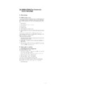
9 – 2
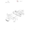
S001
External view section
Section
Unit
Part
JOB
CODE
After-work
NOTE
S No.
Part name
Ua No.
Unit name
Ub No.
Unit name
P No.
Part name
JOB No.
S 001
External view
(Cabinet/Cover)
(Cabinet/Cover)
P 001
Rear cabinet
ASS
P 002
Front upper cabinet
ASS
P 003
Right cabinet
ASS
P 004
Left cabinet
ASS
CLN
CLN
P 005
Front right lower cabinet
ASS
P 006
Front left lower cabinet
ASS
P 007
Document table glass
ASS
CLN
CLN
P 008
Bottom base plate
ASS
P 009
Paper reception tray
ASS
S001/P001
S001/P007/CLN
S001/P003
S001/P005
S001/
P002
P002
S001/P006
S001/P004/CLN
9 – 3
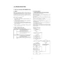
S001/P001
Rear cabinet
(1)
Remove the screw and remove the rear cabinet (S001/P001) in
the arrow direction.
the arrow direction.
*
Troubles caused by improper work
1) Paper detector malfunction
S001/P002
Front upper cabinet
(1)
Open the operation unit and remove the screw. Remove the
front upper cabinet (S001/P002) in the arrow direction.
front upper cabinet (S001/P002) in the arrow direction.
*
Troubles caused by improper work
1) The operation unit cannot be closed completely.
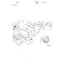
S001/P009
S001/P008
S001/P001
S001/P002
9 – 4

