Sharp AL-800 (serv.man6) Service Manual ▷ View online
*
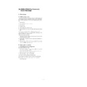
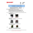
Troubles caused by improper work
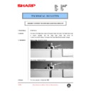
1) Copy (print) defective
(Insufficient density, background copy, dirt, etc.)
(Ghost)
2) The copy density cannot be adjusted with SIM 46-1.
*
Necessary tools
Name
Digital multi-meter/High voltage probe
Parts code/Price rank
—
Note
Internal impedance of 1000M
Ω
or
above, efffective value measurement
(Recommendable unit: FLUKE 87/
FLUKE 80K-40)
(Recommendable unit: FLUKE 87/
FLUKE 80K-40)
*
Note
1) Use a digital multi-meter (effective value meter, internal im-
pedance of 1000M
Ω
or above).
If the above conditiosn are not satisfied, the proper measurement
of voltage cannot be made.
of voltage cannot be made.
2) Since a high voltage is outputted, be careful of electric shock.
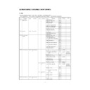
ADJ M7
Fusing temperature adjustment
Content
ADJ M7 Fusing temperature
adjustment
ADJ 1
Fusing temperature
adjustment within 20
sheets of continuous print
adjustment within 20
sheets of continuous print
ADJ 2
Fusing temperature
adjustment after 20 sheets
of continuous print
adjustment after 20 sheets
of continuous print
ADJ 1
Fusing temperature adjustment within 20
sheets of continuous printing
sheets of continuous printing
ADJ 2
Fusing temperature adjustment after 20
sheets of continuous printing
sheets of continuous printing
*
Adjustment value
(Test command (simulation) adjustment value)
Fusing temperature adjustment within 20 sheets of continuous print-
ing
ing
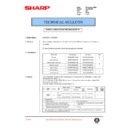
Range (MIN)
1 (155°C)
Range (MAX)
5 (175°C)
Standard value
0 (160°C)
Default
0 (160°C)
Fusing temperature adjustment after 20 sheets of continuous printing
Range (MIN)
1 (150°C)
Range (MAX)
5 (175°C)
Standard value
2 (155°C)
Default
2 (155°C)
(Adjustment value)
Fusing temperature adjustment within 20 sheets of continuous print-
ing
ing
Adjust to 160°C.
Fusing temperature adjustment after 20 sheets of continuous printing
Adjust to 155°C.
*
Program used
Fusing temperature adjustment within 20 sheets of continuous print-
ing
ing
Test command (Simulation)
MODE
Normal
MAIN CODE
43
SUB CODE
1
Fusing temperature adjustment after 20 sheets of continuous printing
Test command (Simulation)
MODE
Normal
MAIN CODE
43
SUB CODE
4
*
Execution time
Enforcement
time
time
JOB No
Content
S 009/Ua 002
When replacing MCU PWB
In case of U2 trouble
Cycle
—
Condition
—
*
Job content
(Fusing temperature adjustment within 20 sheets of continuous print-
ing)
ing)
1) Enter SIM 43-1 mode.
(The currently set code of the fusing temperature adjustment
within 20 sheets of continuous printing is displayed.)
within 20 sheets of continuous printing is displayed.)
2) Set the adjustment value to 0 (160°C) and press the start button.
(Fusing temperature adjustment after 20 sheets of
continuous printing)
continuous printing)
1) Enter SIM 43-4 mode.
(The currently set code of the fusing temperature adjustment after
20 sheets of continuous printing is displayed.)
20 sheets of continuous printing is displayed.)
2) Set the adjustment value to 1 (155°C) and press the start button.
*
Trouble caused by improper work
1) Fusing abnormality
2) Fusing section parts damage
3) Paper jam
*
Note
Be sure to set to the standard value. If not a trouble may occur.
7 – 17
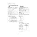
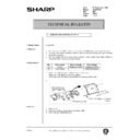
ADJ M8
Power voltage adjustment
*
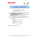
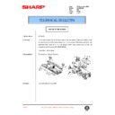
Location
*
Adjustment value
Range (MIN)
23.5V
Range (MAX)
24.5V
Standard value
24V
*
Execution time
Enforcement
time
time
JOB No
Content
S 009/Ua 001
When replacing a power in the
PWB unit.
PWB unit.
*
Necessary condition
1) Adjust with the AC power voltage in the specified range (90
∼
110% of the standard power voltage).
*
Job content
1) Manually turn on the cabinet switch.
2) Turn on the power.
3) Put a digital multi-meter between the check point (24V) on the
power PWB and GND.
4) Turn the adjustment volume (VR601) on the power PWB and
adjust the 24V output to 24
±
0.5V.
*
Trouble caused by improper job
1) Circuit malfunction
2) Circuit parts damage
*
Necessary tool
Name
Digital multi-meter
Parts code/Price rank
—
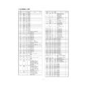
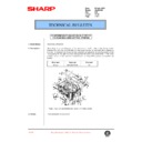
ADJ M9
Copy lamp light quantity adjustment
*
Location value
Range (MIN)
3.9 V
Range (MAX)
4.1 V
Standard value
4.0 V
Default
4.0 V
*
Program used
Test command (Simulation)
MODE
Normal
MAIN CODE
63
SUB CODE
1
*
Enforcement time
Enforcement
time
time
JOB No
Content
S 004/Ua 001/
P 002
P 002
When replacing the scanner
(copy) lamp control PWB
(copy) lamp control PWB
When replacing the copy lamp
In case of E7 (05) trouble
In case of E7 (04) trouble
In case of E7 (12) trouble
In case of E7 (15) trouble
Cycle
—
Condition
Normal copy exposure is not
obtained.
obtained.
*
Necessary condition
1) The scanner section must be clean.
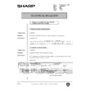
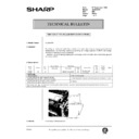
ADJ M8(VR601)
7 – 18
*
Job content
1) Put an oscilloscope between the check point JP3 (VIN) on the
MCU (PCU) PWB and GND.
At that time, trigger with the SH (JP4) signal to see the waveform
correctly.
At that time, trigger with the SH (JP4) signal to see the waveform
correctly.
2) Execute simulation 63-1. (The copy lamp lights up in the scanner
unit home position.)
3) Turn and adjust the volume on the copy lamp drive PWB so that
the CCD output waveform max. value is 4.0
±
0.1 V.
*
Trouble caused y improper operation
1) E7 (05) trouble
2) E7 (04) trouble
3) E7 (12) trouble
4) E7 (15) trouble
5) Copy exposure cannot be adjusted.
6) Copy exposure abnormality
*
Preliminary work
JOB No
Content
S 004
Scanner (reading) section cleaning
*
After-work
JOB No
Content
ADJ M1
Copy exposure adjustment
*
Necessary tools
Name
Oscilloscope
Parts code/Price rank
—
Adjustment VR
4.0±0.1V
7 – 19
*
Job content
1) Put an oscilloscope between the check point JP3 (VIN) on the
MCU (PCU) PWB and GND.
At that time, trigger with the SH (JP4) signal to see the waveform
correctly.
At that time, trigger with the SH (JP4) signal to see the waveform
correctly.
2) Execute simulation 63-1. (The copy lamp lights up in the scanner
unit home position.)
3) Turn and adjust the volume on the copy lamp drive PWB so that
the CCD output waveform max. value is 4.0
±
0.1 V.
*
Trouble caused y improper operation
1) E7 (05) trouble
2) E7 (04) trouble
3) E7 (12) trouble
4) E7 (15) trouble
5) Copy exposure cannot be adjusted.
6) Copy exposure abnormality
*
Preliminary work
JOB No
Content
S 004
Scanner (reading) section cleaning
*
After-work
JOB No
Content
ADJ M1
Copy exposure adjustment
*
Necessary tools
Name
Oscilloscope
Parts code/Price rank
—
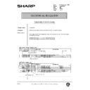
Adjustment VR
4.0±0.1V
7 – 19

