Sharp AL-800 (serv.man5) Service Manual ▷ View online
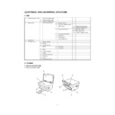
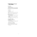
[5] EXTERNAL VIEW AND INTERNAL STRUCTURE
1. List
A
External, operation parts
(1)
External, operation parts
(2)
Internal operation parts
(3)
Operation, display parts
B
Internal parts
(1)
Parts in each section
a
Operation section
b
Paper feed, transport section
c
Optical section
<1>
Scanner (reading) section
<2>
Scanner (writing) section
d
Image process section
<1>
OPC drum section
<2>
Developing section
<3>
Transfer, separation section
e
Fusing, paper exit section
f
Drive section
g
Printer section
h
Cross sectional view
C
Lock position
D
Functional parts
(1)
Sensor, detector
(2)
Switch
(3)
Clutch, solenoid
(4)
Motor
a
Drive motor
b
Fan (motor)
(5)
PWB
(6)
Fuse, thermostat
(7)
Lamp
(8)
Interface (connector)
(9)
Belt, wire
(10)
Power
(11)
Adjustment volume
2. Contents
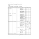
A. External, operation parts
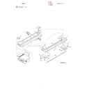
(1) External, operation parts
1)
5)
4)
3)
2)
11)
10)
6)
7)
9)
8)
5 – 1
No.
Parts
Model
Note
Name
Function/Operation
1
Document cover
2
Front cover
Opened when installing or removing the OPC
cartridge and the developer cartridge or
removing a paper jam.
cartridge and the developer cartridge or
removing a paper jam.
3
Paper exit tray
Receives printed paper.
4
Operation panel
Allows various setting in the copy mode and
test command operations.
test command operations.
5
Document table
A document is set to the left corner reference.
6
Paper feed tray
Sets print paper.
7
Paper guide
Adjusts the paper width.
8
Power switch
Turns on/off the main power.
9
Power connector
Connects with the AC power cord.
10
Printer interface connector
Connects with the host computer. (Parallel
interface) (IEEE-1284)
interface) (IEEE-1284)
Allows connection with two host
computers.
computers.
11
Paper release lever
Put the lever straight when setting paper to
release paper feed drive. Put the lever down to
allow paper feed.
release paper feed drive. Put the lever down to
allow paper feed.
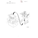
(2) Internal operation parts
No.
Parts
Model
Note
Name
Function/Operation
1
Developer cartridge
Converts latent electrostatic images into visible
images (toner images).
images (toner images).
Common
Life (3K print)
2
OPC cartridge
Forms latent electrostatic images.
Common
Life (20K print)
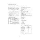
(3) Operation, display parts
1)
2)
1
AUTO
MANUAL
PHOTO
50%
70%
86%
100%
200%
A4
ZOOM
ONLINE
PRE-HEAT
A5
A4
B5
100%
B5
MAX.
MIN.
A4
3 5
115%
(12)
(13)
(14)
(15)
11)
10)
9)
8)
7)
6)
4)
3)
5)
2)
1)
5 – 2
No.
Parts
Model
Note
Name
Function/Operation
1
Copy image mode select
key/Copy image mode
display lamp
key/Copy image mode
display lamp
Selects the copy image mode in auto,
character, photo, toner save mode. Displays
the copy image mode.
character, photo, toner save mode. Displays
the copy image mode.
2
Copy density adjustment
key/Copy density level
display lamp
key/Copy density level
display lamp
Selects the copy density. Used to set the
power save mode. Displays the copy density
mode (level).
power save mode. Displays the copy density
mode (level).
3
Developer cartridge
warning lamp
warning lamp
Turns on or blinks to show that the consumable
part (developer cartridge) must be replaced.
part (developer cartridge) must be replaced.
Turns on when there is little toner, and
blinks when there is no toner to disable
printing.
blinks when there is no toner to disable
printing.
4
OPC cartridge warning
lamp
lamp
Turns on or blinks to show that a consumable
part (developer cartridge, OPC cartridge) or
that there is a paper jam.
part (developer cartridge, OPC cartridge) or
that there is a paper jam.
At 19,000 print, the lamp lights up to
show the life is up. At 20,000 print, the
lamp lights up to disable printing.
show the life is up. At 20,000 print, the
lamp lights up to disable printing.
5
Paper jam warning lamp
Turns on or blinks when there is a paper jam.
6
Copy magnification ratio
select key/Copy
magnification ration display
lamp
select key/Copy
magnification ration display
lamp
Selects the copy magnification ratio.
7
Zoom mode display lamp
Turns on when the zoom key is used to set the
coy magnification ratio.
coy magnification ratio.
8
Copy magnification display
key
key
Used to display the copy magnification ratio set
by the zoom key on the value display.
by the zoom key on the value display.
9
Value, code display LED
Displays the value information (copy quantity,
copy magnification ratio, etc.) and codes (error
code, test command code and its information).
copy magnification ratio, etc.) and codes (error
code, test command code and its information).
10
On-line lamp
Turns on during operation in the printer mode.
(Print data is received from the host in the
printer enable state or during printing.)
(Print data is received from the host in the
printer enable state or during printing.)
11
Pre-heat mode display
lamp
lamp
Blinks in the pre-heat mode.
12
Zoom key
Sets the copy magnification ratio in the range
of 50%
of 50%
∼
200% by the increment of 1%.
13
Value setting key
Used to input various set values (copy quantity,
test command setting, power save mode
setting, etc.). Used to set the power save mode.
test command setting, power save mode
setting, etc.). Used to set the power save mode.
14
Clear key
Cancels various setting and operations.
15
Start key
Starts operations and stores various set data.
Ready lamp
Turns on when in print ready state.
B. Internal parts
(1) Parts in each section
a. Operation section
No.
Parts
Model
Note
Name
Function/Operation
1
Operation control PWB
Displays various number information and
messages. Outputs the key operation signal.
messages. Outputs the key operation signal.
2
Number display
Displays various value information and
messages.
messages.
1)
2)
5 – 3
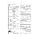
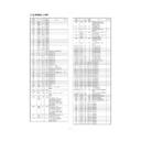
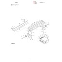
b. Paper feed, transport section
No.
Parts
Note
Code
Signal name
Name
Type
Function/operation
Active condition
1
PE SENSOR
PEMP IN
Paper empty
detector
detector
Photo
transmission
sensor
transmission
sensor
Detects paper on the paper tray.
LOW (0V) when
paper is detected.
paper is detected.
2
Paper guide
Adjust the paper width.
3
Paper feed tray
Sets the print paper. (Capacity:
XXX sheets)
XXX sheets)
4
Paper release
lever
lever
Put this lever straight to set
paper to release paper feed. Put
this lever down to enable paper
feed.
paper to release paper feed. Put
this lever down to enable paper
feed.
5
PUS
PUS
Paper feed clutch
solenoid
solenoid
Controls (on/off) the main motor
drive for the paper feed roller.
drive for the paper feed roller.
6
Paper feed
release lever
release lever
When the paper feed lever is put
straight, this lever releases
paper feed solenoid drive. This
lever reduces stress to the paper
feed roller clutch in removing
paper.
straight, this lever releases
paper feed solenoid drive. This
lever reduces stress to the paper
feed roller clutch in removing
paper.
7
PIN SENSOR PIN
Paper in detector
Photo
transmission
sensor
transmission
sensor
Detects whether the fed paper is
transported to the transfer
position or not. By the timing of
this detector signal, the relative
positions of paper and print
image are controlled.
transported to the transfer
position or not. By the timing of
this detector signal, the relative
positions of paper and print
image are controlled.
LOW (0V) when
paper is detected.
paper is detected.
8
Paper feed roller
Feeds paper.
9
PAPER SIZE
SW
SW
PAPER SIZE
IN
IN
Paper width
detector
detector
Mechanical
switch (Micro
switch)
switch (Micro
switch)
Detects the paper width. This
signal controls the laser beam
radiation area.
signal controls the laser beam
radiation area.
LOW (0V) when
the max. width is
detected.
the max. width is
detected.
10
Paper pressure
plate
plate
Presses paper onto the paper
feed roller.
feed roller.
2)
1) PE SENSOR
3)
4)
5) PUS
6)
7) PIN SENSOR
8)
11)
4)
9) PAPER SIZE SW
6)
12)
13)
14)
12)
8)
13)
15)
17)
16)
16)
18)
10)
19)
19)
5 – 4

