Sharp PN-A601 (serv.man3) Service Manual ▷ View online
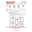
CHAPTER 7. TROUBLESHOOTING
PN-A601 TROUBLESHOOTING
7 – 2
1. THE POWER IS NOT SUPPLIED (THE LED DOES NOT LIGHT UP)
Is the AC cord properly inserted?
No
Insert the AC cord properly.
Is the power SW turned ON?
Is the power SW free from any abnormality?
Is the power SW free from any abnormality?
No
Replace the abnormal part.
Yes
Yes
Replace the abnormal part.
Replace the I/F PWB.
Replace the I/F PWB.
No abnormality
No abnormality
Replace the abnormal part.
Replace the abnormal part.
No abnormality
Abnormality
No abnormality
Abnormality
Abnormality
Check the power cable.
Check the fuse for breakage.
Check the I/F PWB.
Check the fuse for breakage.
Check the I/F PWB.
Check the key PWB and the related parts for any
abnormality.
Check the connection cable.
Check the key PWB.
abnormality.
Check the connection cable.
Check the key PWB.
Check the I/F PWB and the related parts for any
abnormality.
abnormality.
Replace the abnormal part.
Replace the LED-TCON PWB.
Replace the LED-TCON PWB.
Abnormality
Check the power cable, signal cable.
Check the LED-TCON PWB.
Check the LED-TCON PWB.
Check the LED-TCON PWB and the related parts
for any abnormality.
for any abnormality.
No abnormality
Replace the abnormal part.
Replace the LED driver PWB.
Reinsert the FFC harness.
Abnormality
Check the power cable, signal cable.
Check that the FFC cable is not inserted diagonally.
Check the fuse for breakage.
Check the LED driver PWB.
Check that the FFC cable is not inserted diagonally.
Check the fuse for breakage.
Check the LED driver PWB.
Check the LED driver PWB and the related parts for
any abnormality.
any abnormality.
CAUTION
Any problem with the Power Supply PWB
related items?
related items?
ȷIs the fuse blown?
ȷAny problem with the Power Supply PWB?
ȷAny problem with the switch cable?
ȷAny problem with the AC relay PWB?
ȷAny problem with the AC power cord?
ȷAny problem with the Power Supply PWB?
ȷAny problem with the switch cable?
ȷAny problem with the AC relay PWB?
ȷAny problem with the AC power cord?
Are 13.5V, BU5V, and 12V outputted from the system
power PWB, and is 24V power outputted from the LED
power PWB?
power PWB, and is 24V power outputted from the LED
power PWB?
When the signal is not inputted, the power save
function operates to shut off 13.5V, BU5V, and 12V
from the system power and 24V from the LED
power PWB.
function operates to shut off 13.5V, BU5V, and 12V
from the system power and 24V from the LED
power PWB.
Since the backlight is turned off when inputting in
the whole-black screen in the local dimming mode,
check the input image.
the whole-black screen in the local dimming mode,
check the input image.
CHAPTER 7. TROUBLESHOOTING
PN-A601 TROUBLESHOOTING
7 – 3
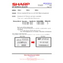
2. OPTIONAL POWER IS NOT TURNED ON
3. THE REMOTE CONTROL DOES NOT WORK
Is the OSD setting properly configured?
No abnormality
No
No
Yes
No abnormality
Is 19V power output from the system power PWB?
Check the connected optional devices.
Configure the OSD setting again.
Replace the defective part.
Any problem with the Power Supply PWB
related items?
related items?
ȷIs the fuse blown?
ȷAny problem with the Power Supply PWB?
ȷAny problem with the Power Supply PWB?
Is the battery power alive?
Is the adjustment lock of "FUNCTION" set to [disabled]?
No abnormality
Yes
Yes
Consumption
No
No
Replace the battery.
Is the OSD set to non-display?
Set to ENABLE the OSD display (special function).
Clear the setting.
Is the control kit connected?
Yes
No
1
Is the control kit setting set to "External"?
Yes
No
Set the control kit to "External."
Replace the abnormal part.
Connect the cable to the proper terminal.
Connect the cable to the proper terminal.
Replace the abnormal part.
No abnormality
Abnormality
Abnormality
Any problem with the Control Kit or connection cable?
Any problem with the connection cable?
Any problem with the PWB?
Is the control kit cable is connected to the sound
terminal?
Any problem with the connection cable?
Any problem with the PWB?
Is the control kit cable is connected to the sound
terminal?
Check the I/F PWB and the related parts for any
abnormality.
Check the fuse for breakage.
Check the PWB.
abnormality.
Check the fuse for breakage.
Check the PWB.
1
Is the control kit setting set to "Built-in"?
Yes
No
Set the control kit to "Built-in."
Replace the abnormal part.
Replace the abnormal part.
No abnormality
Abnormality
Abnormality
Any problem with the key PWB or connection cable?
Any problem with the connection cable?
Any problem with the key PWB?
Any problem with the connection cable?
Any problem with the key PWB?
Check the I/F PWB and the related parts for any
abnormality.
Check the fuse for breakage.
Check the PWB.
abnormality.
Check the fuse for breakage.
Check the PWB.
CHAPTER 7. TROUBLESHOOTING
PN-A601 TROUBLESHOOTING
7 – 4
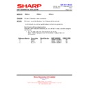
4. THE DISPLAY DOESN’T SHOW/ DISPLAY ABNORMALITY
Check the adjustment and setting for any abnormality.
Readjust and reset with the menu.
Is input selection set to signal input?
Adjust the input source properly.
Replace the graphic board.
Check the connected devices.
Check the connected devices.
Replace the abnormal part.
Replace the defective part.
Is the menu displayed under the signal input state?
Replace the LCD module.
No abnormality
Yes
No abnormality
Yes
Yes
Abnormality
Abnormality
Abnormality
No abnormality
Abnormality
No
No
No
HDMI connection only
Any defect with the connected devices?
Is the graphic board resolution proper?
Any defect with the connected devices?
Is the graphic board resolution proper?
Check the I/F PWB and the related parts.
Check the connection cable.
Check the fuse for breakage.
Check the PWB.
Check the connection cable.
Check the fuse for breakage.
Check the PWB.
Check the video input signal for any abnormality.
Check the video cable.
Check that the video signal is not a special one
(out of support).
Check the video cable.
Check that the video signal is not a special one
(out of support).
Check the LCD module and the related parts for any
abnormality.
Check the connection cable.
Check the LCD control PWB.
abnormality.
Check the connection cable.
Check the LCD control PWB.
Any problem with the I/F board related items?
Any problem with the connection cable?
Is the fuse blown?
Any problem with the PWB?
Any problem with the connection cable?
Is the fuse blown?
Any problem with the PWB?
Replace the defective part.
Connect the cable properly.
Abnormality
No abnormality
Any problem with the connection cable?
Any problem with the PWB?
Any problem with the PWB?
Check the LED-TCON PWB and the related parts
for any abnormality.
for any abnormality.
CHAPTER 7. TROUBLESHOOTING
PN-A601 TROUBLESHOOTING
7 – 5
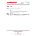
5. NO IMAGE IS DISPLAYED/ DISPLAY FAILURE (EXTENSION INTERFACE)
Any problem with the adjustment/ settings?
No abnormality
No abnormality
No abnormality
Does the signal input correspond to the selected input?
Yes
Yes
Yes
Is the menu displayed with the signal being input?
Replace the expansion board.
Abnormality
Make readjustment/ resetting from the menu.
Select the input source properly.
Replace the graphic board.
Check the connected devices.
Check the connected devices.
Replace the defective part.
Replace the defective part.
Abnormality
Abnormality
No
No
No
DVI connection only
Any problem with the connected devices?
Any problem with the resolution of graphic board?
Any problem with the connected devices?
Any problem with the resolution of graphic board?
Any defect with the LCD module and related devices?
Any defect with the connecting cable?
Any defect with the LCD control PWB?
Any defect with the connecting cable?
Any defect with the LCD control PWB?
Any defect with the video input signal of BNC?
Any problem with the terminal setting?
Is the BNC connection proper?
Any defect with the video cable?
Is the video signal a particular kind? (Out of support)
Any problem with the terminal setting?
Is the BNC connection proper?
Any defect with the video cable?
Is the video signal a particular kind? (Out of support)
Any defect with the I/F PWB and related
devices?
Any defect with the connecting cable?
Did the fuse blow out?
Any defect with the PWB?
devices?
Any defect with the connecting cable?
Did the fuse blow out?
Any defect with the PWB?


