Sharp LL-T1610W (serv.man3) Service Manual ▷ View online
CHAPTER 2. CONNECTION, ADJUSTMENT, OPERATION AND FUNCTIONS
1. CONNECTING THE MONITOR AND
TURNING THE MONITOR ON AND OFF
1-1. CONNECTING THE MONITOR TO A POWER
SOURCE
Use only the AC adapter and power cord supplied.
Notes:
•
Do not overly bend the cable or add extension cords as
this could lead to malfunction.
this could lead to malfunction.
•
Do not remove the label next to the power-input terminal.
Also do not touch the switch covered by the label.
Also do not touch the switch covered by the label.
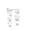
1. Remove the rear cover.
2. Remove the stand cover.
As in the diagram below, place two fingers on the stand cover and
while pushing the section
while pushing the section
, pull it forwards
.
3. Remove the adapter cover.
While pushing the section
, pull it forwards and off
.
4. Connect the AC adapter to the monitor’s power terminal, and
connect the power cord to the AC adapter.
5. Place the AC adapter inside the stand.
Wind the AC adapter cable and place it in the right-hand end of
the stand
the stand
.
Place the AC adapter inside
. When doing this be careful not
to place the AC adapter on top of the cable as this will make it
difficult to replace the adapter cover.
difficult to replace the adapter cover.
Run the AC adapter cable between the AC adapter and the stand
.
6. Replace the adapter cover.
Rear cover
1
1
2
2
1
CAUTION!
Be careful not to
cut or jam your
fingers.
Be careful not to
cut or jam your
fingers.
Stand cover
3
4
Adapter cover
Power cord
AC adapter
Run cord
through hole
through hole
6
7
5
8
Note: Take care not bend
or twist the cord
Run the AC adapter
cord through here.
cord through here.
Run the powerr cord through here.
7. Replace the stand cover.
8. Replace the rear cover.
9. Place power plug into AC outlet.
1-2. CONNECTING THE MONITOR TO A
COMPUTER (PC ETC.)
For analog RGB output terminal
Connecting to a computer with analog RGB output. When connecting,
ensure that both the monitor and computer are switched off.
ensure that both the monitor and computer are switched off.
Notes:
•
If using the monitor for the first time or after having
changed the system settings during use, perform an auto-
matic screen adjustment.
changed the system settings during use, perform an auto-
matic screen adjustment.
•
Be careful not to overly bend the cable or add extension
cords as this could lead to malfunction.
cords as this could lead to malfunction.
•
When connecting to a notebook, if the notebook com-
puter’s screen is set so that it is displaying at the same
time, the MS-DOS screen may not be able to display
properly. In this case, change the settings so that only the
monitor is displaying.
puter’s screen is set so that it is displaying at the same
time, the MS-DOS screen may not be able to display
properly. In this case, change the settings so that only the
monitor is displaying.
Note: If connecting to the Sun Ultra series, a conversion adapter
(purchased separately) may be required.
For digital RGB output terminal
Connecting to a computer with digital RGB output. When connecting,
ensure that both the monitor and computer are switched off.
ensure that both the monitor and computer are switched off.
Notes:
•
A computer with an output terminal conforming to DVI
(DVI-D24 pin or DVI-I29 pin) and with SXGA output capa-
bility can be connected here. Depending on the type of
computer to be connected, the display may not work cor-
rectly. In order to connect, it is necessary to purchase a
digital signal cable separately. (model name: NL-C01E)
(DVI-D24 pin or DVI-I29 pin) and with SXGA output capa-
bility can be connected here. Depending on the type of
computer to be connected, the display may not work cor-
rectly. In order to connect, it is necessary to purchase a
digital signal cable separately. (model name: NL-C01E)
•
Be careful not to overly bend the cable or add extension
cords as this could lead to malfunction.
cords as this could lead to malfunction.
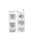
1. Remove the rear cover and the stand cover.
To remove them follow steps 1 and 2 of Connecting the monitor
to a power source.
to a power source.
2. Attach the digital signal cable (sold separately from monitor).
If you are not using the analog signal cable, you can remove it.
Loosen all screws on the plug and disconnect it.
Loosen all screws on the plug and disconnect it.
9
10
Run the analog signal
cable through here.
cable through here.
12
11
Analog signal cable
Computer
Analog RGB output terminal (mini D-sub 15 pin
with 3 rows)
Firmly insert the plug then tighten the screws
each side.
with 3 rows)
Firmly insert the plug then tighten the screws
each side.
If connecting to a D-sub 15 pin 2 row Apple Power
Macintosh, attach a Macintosh conversion adapter (to
be purchased separately) to the analog signal cable.
Macintosh, attach a Macintosh conversion adapter (to
be purchased separately) to the analog signal cable.
Macintosh
conversion adapter
conversion adapter
Analog signal cable
After connecting the adapter, tighten the
screws on each side to fix into place
After connecting the adapter, tighten the
screws on each side to fix into place
Digital signal input terminal (DV-D24 pin)
Firmly insert the plug than tighten the screws
each side.
Firmly insert the plug than tighten the screws
each side.
Run cable through hole
Digital signal cable
Analog signal cable
3. Replace the stand cover.
4. Replace the rear cover.
To replace it follow step 8 of Connecting the monitor to a power
source.
source.
5. Connect the digital signal cable to the computer.
Note: After turning the monitor on, use the INPUT button to switch
the incoming signal over to DIGITAL.
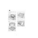
1-3. TURNING THE POWER ON
1. Press the monitor’s power button.
2. Turn on the computer.
The power LED will be lit green, and the screen will display an
image.
image.
Switching between input signals
To obtain the desired signal use the INPUT button to switch over to it.
Within a matter of seconds the signal type will be displayed on the
upper right-hand part of the screen.
Within a matter of seconds the signal type will be displayed on the
upper right-hand part of the screen.
Installing set-up information and the ICC profile
(Windows)
(Windows)
Depending on the computer or OS, it may be necessary to use the
computer to operate the installation of monitor set-up information etc.
If so, follow the steps below to install the monitor set-up information.
(Depending on the type of computer or OS, command names and
methods may differ. Please follow the computer’s own operation
manual while reading this.)
computer to operate the installation of monitor set-up information etc.
If so, follow the steps below to install the monitor set-up information.
(Depending on the type of computer or OS, command names and
methods may differ. Please follow the computer’s own operation
manual while reading this.)
About the ICC profile
An ICC (International Color Consortium) profile is a file that describes
the color characteristics of the LCD monitor. By using an application
that works together with an ICC profile, a high color resolution can be
realized.
the color characteristics of the LCD monitor. By using an application
that works together with an ICC profile, a high color resolution can be
realized.
•
Windows98, WindowsMe and Windows2000 all use the ICC pro-
file.
file.
•
When installing Windows98, WindowsMe and Windows2000 set-
up information (described below), the ICC profile is also installed. If
you would like to install the ICC program only, please refer to
Installing the ICC profile.
up information (described below), the ICC profile is also installed. If
you would like to install the ICC program only, please refer to
Installing the ICC profile.
•
When using the ICC profile, please set the [WHITE BALANCE] to
[STD] and the [COLOR MODE] to [OFF].
[STD] and the [COLOR MODE] to [OFF].
■
For Windows95
Installing monitor set-up information into Windows95.
This explanation assumes that the floppy disk drive is "A drive".
This explanation assumes that the floppy disk drive is "A drive".
1.
Place the Utility Disk (provided) into the computer’s A drive.
2.
Click on the [Start] button. From [Settings], choose [Control
Panel].
Panel].
3.
Double click on [Display].
4.
Click on [Settings], [Advanced Properties], and [Monitor], then
[Change].
[Change].
5.
Click on [Have disk], confirm that [Copy manufacturer’s files
from:] is [A:] then click [OK].
from:] is [A:] then click [OK].
6.
Confirm that the monitor details are selected, and click [OK].
7.
Check that the monitor details are displayed, then click [Apply].
8.
Click [OK], and close the window.
9.
Remove the Utility Disk from the A drive.
■
For Windows98
Installing monitor set-up information into Windows98, and setting the
monitor’s ICC profile as a predetermined value.
This explanation assumes that the floppy disk drive is "A drive".
monitor’s ICC profile as a predetermined value.
This explanation assumes that the floppy disk drive is "A drive".
If the "Add new Hardware Wizard" has appeared:
1.
Place the Utility Disk (provided) into the computer’s A drive.
2.
Click [Next].
3.
Check [Display a list of all the drivers in a specific location, so
you can select the driver you want.], then click [Next].
you can select the driver you want.], then click [Next].
4.
When [Models] is displayed, click on [Have disk], confirm that
[Copy manufacturer’s files from:] is [A:], and click [OK].
[Copy manufacturer’s files from:] is [A:], and click [OK].
5.
Confirm that the monitor details are selected, then click [Next],
[Next], and [Finish]. If the "Add New Hardware Wizard" appears,
repeat the installation commands beginning from 2 above.
[Next], and [Finish]. If the "Add New Hardware Wizard" appears,
repeat the installation commands beginning from 2 above.
6.
Remove the Utility Disk from the A drive.
If the "Add New Hardware Wizard" has not appeared:
1.
Place the Utility Disk in the computer’s A drive.
2.
Click on the [Start] button. From [Settings], choose [Control
Panel].
Panel].
3.
Double click on [Display].
1
2
Run the digital signal
cable or the analog
signal cable through
here
cable or the analog
signal cable through
here
Digital RGB output terminal (DVI-D24 pin
or DVI-129 pin)
Firmly insert the plug then tighten the
screw each side.
or DVI-129 pin)
Firmly insert the plug then tighten the
screw each side.
Computer
Digital signal cable
Power LED
Power button
INPUT
INPUT
DIGITAL
ANALOG
Analog signal
Digital signal
4.
Click on [Settings], [Advanced] and [Monitor].
5.
In [Options], check [Automatically detect Plug & Play monitors]
and click on [Change].
and click on [Change].
6.
Click [Next].
7.
Click on [Display a list of all the drivers in a specific location, so
you can select the driver you want.], then click [Next].
you can select the driver you want.], then click [Next].
8.
When [Models] is displayed, click on [Have disk], confirm that
[Copy manufacturer’s files from:] is [A:], and click [OK].
[Copy manufacturer’s files from:] is [A:], and click [OK].
9.
Confirm that the monitor details are selected, then click [Next],
[Next], and [Finish].
[Next], and [Finish].
10. Check that the monitor details are displayed, then click [Apply].
11. Click [OK], and close the window.
12. Remove the Utility Disk from the A drive.
■
For Windows2000
Installing monitor set-up information into Windows2000, and setting
the monitor’s ICC profile as a predetermined value.
the monitor’s ICC profile as a predetermined value.
This explanation assumes that the floppy disk drive is "A drive".
1.
Place the Utility Disk (provided) into the computer’s A drive.
2.
Click on the [Start] button. From [Settings], choose [Control
Panel].
Panel].
3.
Double click on [Display].
4.
Click on [Settings], [Advanced] and [Monitor].
5.
Click on [Properties], [Driver] and [Update Driver].
6.
When [Upgrade Device Driver Wizard] appears, click [Next].
7.
Check [Display a list of the known drivers for this device so that I
can choose a specific driver] and click [Next].
can choose a specific driver] and click [Next].
8.
When [Models] is displayed, click on [Have disk], confirm that
[Copy manufacturer’s files from:] is [A:], and click [OK].
[Copy manufacturer’s files from:] is [A:], and click [OK].
9.
Select the monitor from the list displayed and click [Next].
10. Click [Next], confirm that the monitor’s name appears on the
screen, and click [Finish]. If [The Digital Signature Not Found]
appears, click [Yes].
appears, click [Yes].
11. Click on [Close].
12. Click [OK], and close the window.
13. Remove the Utility Disk from the A drive.
■
For WindowsMe
Installing monitor set-up information into WindowsMe, and setting the
monitor’s ICC profile as a predetermined value.
monitor’s ICC profile as a predetermined value.
This explanation assumes that the floppy disk drive is "A drive".
If the "Add new Hardware Wizard" has appeared:
1.
Place the Utility Disk (provided) into the computer’s A drive.
2.
Check [Specify the location of the driver [Advanced]] and click
[Next].
[Next].
3.
Check [Display a list of all the drivers in a specific location, so
you can select the driver you want.], then click [Next].
you can select the driver you want.], then click [Next].
4.
When [Models] is displayed, click on [Have disk], confirm that
[Copy manufacturer’s files from:] is [A:], and click [OK].
[Copy manufacturer’s files from:] is [A:], and click [OK].
5.
Select the monitor details from the list, then click [Next], [Next],
and [Finish]. If the "Add new Hardware Wizard" appears, repeat
the installation commands beginning from 2 above.
and [Finish]. If the "Add new Hardware Wizard" appears, repeat
the installation commands beginning from 2 above.
6.
Remove the Utility Disk from the A drive.
If the "Add New Hardware Wizard" has not appeared:
1.
Place the Utility Disk in the computer’s A drive.
2.
Click on the [Start] button. From [Settings], choose [Control
Panel].
Panel].
3.
Double click on [Display].
4.
Click on [Settings], [Advanced] and [Monitor].
5.
In [Options], check [Automatically detect Plug & Play monitors]
and click on [Change].
and click on [Change].
6.
Check [Specify the location of the driver [Advanced]] and click
[Next].
[Next].
7.
Check [Display a list of all the drivers in a specific location, so
you can select the driver you want.] and click [Next].
you can select the driver you want.] and click [Next].
8.
When [Models] is displayed, click on [Have disk], confirm that
[Copy manufacturer’s files from:] is [A:], and click [OK].
[Copy manufacturer’s files from:] is [A:], and click [OK].
9.
Select the monitor details, then click [Next], [Next], and [Finish].
10. Check that the monitor details are displayed, then click [Apply].
11. Click [OK], and close the window.
12. Remove the Utility Disk from the A drive.
Installing the ICC profile
Installing the monitor’s ICC profile. (If the set-up information has al-
ready been installed, so too has the profile, and there is no need to
install it.)
ready been installed, so too has the profile, and there is no need to
install it.)
This explanation assumes that the floppy disk drive is "A drive".
1.
Place the Utility Disk in the computer’s A drive.
2.
Click on the [Start] button. From [Settings], choose [Control
Panel].
Panel].
3.
Double click on [Display].
4.
Click on [Settings] and [Advanced].
5.
Click on [General] and from [Compatibility] select [Apply the new
display setting without restarting], then click on [Color Manage-
ment].
display setting without restarting], then click on [Color Manage-
ment].
6.
Click [Add], and select [3
1
/
2
Floppy [A:]] as the file location.
7.
Choose the color profile that you would like to install, and click
on [Add].
on [Add].
8.
Choose the profile and click on [Set As Default].
9.
Click [OK], and close the window.
10. Remove the Utility Disk from the A drive.
•
When using the ICC profile, please set the [WHITE BALANCE] to
[STD] and the [COLOR MODE] to [OFF].
[STD] and the [COLOR MODE] to [OFF].
Information about the ColorSync profile (MacOS)
About the ColorSync profile
ColorSync is the Apple Corporation’s color management system and
is a function that enables color resolution to be realized when used
with a compatible application. A ColorSync profile describes the color
characteristics of the LCD monitor.
is a function that enables color resolution to be realized when used
with a compatible application. A ColorSync profile describes the color
characteristics of the LCD monitor.
Notes:
•
This monitor’s ColorSync profile works with MacOS8.5 or
above.
above.
•
When using the ColorSync profile, please set the [WHITE
BALANCE] to [STD] and the [COLOR MODE] to [OFF].
BALANCE] to [STD] and the [COLOR MODE] to [OFF].

