Sharp LL-T1610W (serv.man6) Service Manual ▷ View online
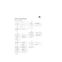
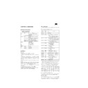
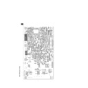
CHAPTER 4. TROUBLESHOOTING
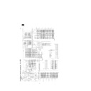
Nothing is displayed on screen
Yes
No
Go to procedure
2
.
Yes
No
Go to procedure
3
.
Yes
No
Go to procedure
4
.
Yes
No
Go to procedure
5
.
No
Yes
Check M62334FP
(main PWB IC19)
and its peripheral circuits.
(main PWB IC19)
and its peripheral circuits.
No
Yes
RESET (main PWB IC3)
operates with power ON?
operates with power ON?
Check MB3111
(main PWB IC3)
and its peripheral circuits.
(main PWB IC3)
and its peripheral circuits.
No
Yes
MCLK (main PWB R6)
oscillates?
oscillates?
Check ICS512
(main PWB IC6)
and its peripheral circuits.
(main PWB IC6)
and its peripheral circuits.
No
Yes
Check flash memory
(main PWB IC27)
and its peripheral circuits.
(main PWB IC27)
and its peripheral circuits.
43.2MHz
Yes
DCLK (main PWB R7)
oscillates (108 MHz)?
oscillates (108 MHz)?
Check ICS511
(main PWB IC1)
and its peripheral circuits.
(main PWB IC1)
and its peripheral circuits.
No
129.6MHz
Go to procedure
3
.
No
Yes
LCD is defective.
LED does not come on.
Go to procedure
1
.
LED (orange) stays in orange.
OSD does not appear with
MENU, INPUT.
MENU, INPUT.
B/L does not come on.
Press "All reset".
3.3 V (main PWB FB202) is
outputted?
outputted?
LEDY or LEDR signal is
outputted?
outputted?
LCD is defective.
MCLK frequencies are
43.2MHz/129.6MHz?
43.2MHz/129.6MHz?
OSD is displayed?
1
2
VON (main PWB CN4,7) are
outputted (High)?
outputted (High)?
Check M62334FP
(main PWB IC19)
and its peripheral circuits.
(main PWB IC19)
and its peripheral circuits.
No
Yes
Inverter PWB is normal?
Inverter PWB is defective.
No
Yes
12 V (main PWB FB201) is
outputted?
outputted?
Check IC2, IP1 and peripheral
circuits.
circuits.
No
Yes
Control signal are outputted to
LCD connector (CN9)?
LCD connector (CN9)?
Check the circuit between
PW164 (IC9) and connector
(CN9).
PW164 (IC9) and connector
(CN9).
Yes
Adapter is defective.
No
Yes
ICP broken (main PWB IP2)?
Replace ICP.
Yes
No
Check IC7 and its peripheral
circuits.
circuits.
Go to procedure
4
.
LCD is defective.
Adapter outputted normal?
No
3
4
5
Nothing is displayed on the PC screen (analog
RGB)
RGB)
Nothing is displayed on the PC screen (digital DVI).
USB is inoperative.
HSYNC and VSYNC are
inputted (LVC126, IC15)?
inputted (LVC126, IC15)?
Go to procedure
6
.
No
Yes
GHS and GVS are outputted
(LVC126, IC15)?
(LVC126, IC15)?
Check the main PWB IC15
and its peripheral circuits.
and its peripheral circuits.
No
Yes
PW164 control signals
(TP102, TP106, TP109) are
outputted?
(TP102, TP106, TP109) are
outputted?
PW164 (main PWB IC9) is
defective.
defective.
No
Yes
5 V (main PWB FB203) is
outputted?
outputted?
Check IC13 and IP3 and their
peripheral circuits.
peripheral circuits.
No
Yes
PVDD and AVDD (main PWB
FB4, FB3) are outputted?
FB4, FB3) are outputted?
Check UPC2933 (IC17, IC10)
and their peripheral circuits.
and their peripheral circuits.
No
Yes
ADC9884 (main PWB IC11)
outputted is generated
(55 -112, 116)
outputted is generated
(55 -112, 116)
ADC9884 (main PWB IC11)
is defective.
is defective.
No
Yes
PW164 (main PWB IC11) is
defective.
defective.
PC is Sync ON Green?
Check main PWB Q502 and
Q503 and their peripheral
circuits.
Q503 and their peripheral
circuits.
Yes
No
Check RGB cable and main
PWB CN6.
PWB CN6.
6
SiI151A outputs GHS and
VSYNC?
(main PWB R26, R25)
VSYNC?
(main PWB R26, R25)
Go to procedure
7
.
No
Yes
GFBK and GVS are outputted?
(main PWB R534, R535)
(main PWB R534, R535)
Check the main PWB IC12
and IC14 and their peripheral
circuits.
and IC14 and their peripheral
circuits.
No
Yes
PW164 control signals
(TP102, TP106, and TP109)
are outputted?
(TP102, TP106, and TP109)
are outputted?
PW164 (main PWB IC9) is
defective.
defective.
No
Yes
5 V (main PWB FB203) is
outputted?
outputted?
Check IC13, IP3 and their
peripheral circuits.
peripheral circuits.
No
Yes
TV 3.3 (main PWB FB5) is
outputted?
outputted?
Check UPC2933 (IC21) and
its peripheral circuits.
its peripheral circuits.
No
Yes
SiI151A (main PWB IC18)
output is generated? (10 - 77)
output is generated? (10 - 77)
SiI151A (main PWB IC18) is
defective.
defective.
No
Yes
PW164 (main PWB IC11) is
defective.
defective.
PC is set for digital outputted
mode?
mode?
No
Yes
Set PC to digital outputted
mode.
mode.
7
Check digital cable and main
PWB CN5.
PWB CN5.
3.3 V output is generated?
(USB PWB IC13 pin)
(USB PWB IC13 pin)
Check regulator
(USB PWB IC1)
and its peripheral circuits.
(USB PWB IC1)
and its peripheral circuits.
No
Yes
Clock is generated
(4 MHz: USB PWB IC3, pin 25)
(4 MHz: USB PWB IC3, pin 25)
Check clock generator
(USB PWB X1)
and its peripheral circuits.
(USB PWB X1)
and its peripheral circuits.
No
Yes
RESET
(USB PWB IC3, pin 6) is High?
(USB PWB IC3, pin 6) is High?
Check USB PWB R3, C203,
and D7.
and D7.
No
Yes
Data input
(USB PWB IC3, pins 7 and 8)?
(USB PWB IC3, pins 7 and 8)?
Check the path from USB
PWB CN1 to IC3.
PWB CN1 to IC3.
No
Yes
Data output
(USB PWB IC3, pins 9, 10, 12,
and 13)?
(USB PWB IC3, pins 9, 10, 12,
and 13)?
Check the path from USB
PWB IC3 to CN2.
PWB IC3 to CN2.
No
Display

