Sharp AE-XM18CR (serv.man16) Service Manual ▷ View online
67
AY-XM7/9/12CR
AY-XPM7/9/12CR
AE-XM18/24CR
AY-XPM7/9/12CR
AE-XM18/24CR
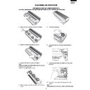
DISASSEMBLING PROCEDURE FOR OUTDOOR UNIT
CAUTION: DISCONNECT THE UNIT FROM POWER SUPPLY BEFORE ANY SERVICING.
(The illustrations are for AE-XM24CR. Construction of AE-XM18CR may differ slightly from the illustration.)
2. Unscrew the 6 screws fixing the side cover R then
remove it
3. Unscrew the 7 screws fixing the cabinet then remove
it.
3 screws are at the left.
2 screws are at the right.
1 screw is at the front.
1 screw is at the rear.
2 screws are at the right.
1 screw is at the front.
1 screw is at the rear.
4. Unscrew the 3 screws fixing the control box angle
then remove it.
CAUTION: DISCHARGE ELECTROLYTIC
CAPACITOR BEFORE TOUCHING THIS
CAPACITOR OR OTHER COMPONENTS
OR WIRINGS.
CAPACITOR OR OTHER COMPONENTS
OR WIRINGS.
5. Cut the 3 wire fixing bands.
6. Disconnect the 8 (AE-XM24CR) or 7 (AE-XM18CR)
connectors.
Expansion valve (CN12A,CN12B,CN12C) : 3pcs.
(AE-XM24CR)
Expansion valve (CN12A,CN12B) : 2pcs.
(AE-XM18CR)
Termistor (CN8A,CN8B) : 2pcs.
Fan motor (CN3) : 1pc.
Reverse valve coil (CN4) : 1pc
Display board unit (CN11) : 1pc
Expansion valve (CN12A,CN12B,CN12C) : 3pcs.
(AE-XM24CR)
Expansion valve (CN12A,CN12B) : 2pcs.
(AE-XM18CR)
Termistor (CN8A,CN8B) : 2pcs.
Fan motor (CN3) : 1pc.
Reverse valve coil (CN4) : 1pc
Display board unit (CN11) : 1pc
Note : Caution to connectors position especially the
expansion valves, when reinstalling
7. Remove the compressor cover B.
Disconnect 5 terminals.
Coil for PFC1 (L1) : 2pcs (White)
Compressor : 3pcs (Red, White and Orange)
Compressor : 3pcs (Red, White and Orange)
Note : Caution to connectors position especially the
compressor, when reinstalling.
1. Unscrew the 3 screws fixing the control box cover
then remove it.
68
AY-XM7/9/12CR
AY-XPM7/9/12CR
AE-XM18/24CR
AY-XPM7/9/12CR
AE-XM18/24CR
8. Unscrew the 13 screws fixing the rear cabinet then
remove it.
1 screw is at the left.
5 screws are at the right.
7 screw is at the rear.
5 screws are at the right.
7 screw is at the rear.
12 .Unscrew the 3 screws fixing the coil for PFC then
remove it
Note : When the coil re-install, silicone grease must
be paste to the back face of the coil.
9. Unfasten the nut fixing the propeller fan then remove
it. Unscrew the 5 screws fixing the control box then
remove it.
remove it.
1 screw is at the right.
4 screws are at the front.
4 screws are at the front.
Note : How to disassemble of control box assembly
is shown in step 15 – 23.
10. Unscrew the 2 screws fixing the fan motor angle
assembly then remove it with lifting up as unhook
the hook on the base pan.
Unscrew the 3 screws fixing the fan bulkhead
assembly then remove.
the hook on the base pan.
Unscrew the 3 screws fixing the fan bulkhead
assembly then remove.
11. Unscrew the 4 screws fixing the fan motor then
remove it.
13. Remove the 3 strings on the compressor cover A
then remove it
14. Remove the 6 thermistors (A3AEXM24CR) or 5
thermistors (AE-XM18CR) on copper tube.
Note : Caution to position when re-installing.
Refer to page 74
(Mounting position of thermistors and expansion valves)
(Mounting position of thermistors and expansion valves)
TH7 (BROWN) : (AE-XM24CR)
TH6 (WHITE) : (AE-XM18CR)
TH6 (WHITE) : (AE-XM18CR)
TH6 (WHITE) : (AE-XM24CR)
TH5 (BLUE) : (AE-XM18CR)
TH5 (BLUE) : (AE-XM18CR)
TH5 (BLUE) : (AE-XM24CR
only)
only)
TH3 (GREEN)
TH4 (BLACK)
TH2 (ORANGE)
69
AY-XM7/9/12CR
AY-XPM7/9/12CR
AE-XM18/24CR
AY-XPM7/9/12CR
AE-XM18/24CR
How to disassemble the control box
assembly
assembly
15. Cut the 3 wire fixing bands.
Disconnect the 5 connectors.
(CN6,CN15,CN5B,CN9B,CN7)
(CN6,CN15,CN5B,CN9B,CN7)
CAUTION: Fix the connector of the power module
securely.
Then lift up the control board unit (PWB) and remove it.
16 .Unscrew the 3 screws fixing the power supply board
unit (PWB).
Unscrew the 1 screw fixing the PTC thermistor.
Unscrew the 1 screw fixing the fan motor capacitor.
Unscrew the 1 screw fixing the PTC thermistor.
Unscrew the 1 screw fixing the fan motor capacitor.
17. Disconnect the 2 terminals (Blue). (A3AEXM24CR
only). Disconnect the 2 terminals (Brown).
And unscrew the 3 screws fixing the terminal board
angle assembly then turn it inside out.
And unscrew the 3 screws fixing the terminal board
angle assembly then turn it inside out.
18. Unscrew the 2 screws fixing the transformer then
remove the power supply board unit (PWB).
19. Disconnect 2 connectors (CN1,CN9). Then lift up the
relay board unit (PWB) and remove it.
Power
transistor
module
transistor
module
NG
OK
20. Unscrew the 2 screws fixing the heat sink cover then
remove it.
70
AY-XM7/9/12CR
AY-XPM7/9/12CR
AE-XM18/24CR
AY-XPM7/9/12CR
AE-XM18/24CR
21. Disconnect the 6 terminals(IN+,IN-,L+,L-,OUT+,
OUT-) and 1 connector (CN13) on the active filter.
And unscrew the 2 screws fixing the active filter and
remove it.
And unscrew the 2 screws fixing the active filter and
remove it.
Note : When the active filter re-install, silicone
grease must be paste to the back face of the
active filter.
active filter.
22. Unscrew the 4 screws fixing the heat sink
Note : Seal the 4 burring holes with silicone sealer
Note : Seal the 4 burring holes with silicone sealer
before re-installing.
23. Disconnect the 5 terminals(P(+),N(-),U,V,W) and 2
connectors (CN5A,CN14) on the power transistor
module (IPM). And unscrew the 4 screws fixing the
power module and remove it.
module (IPM). And unscrew the 4 screws fixing the
power module and remove it.
Note : When the power module re-install, silicone
grease must be paste to the back face of the
power module.
power module.
Click on the first or last page to see other AE-XM18CR (serv.man16) service manuals if exist.

