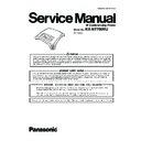
Panasonic KX-NT700RU Service Manual ▷ View online
ORDER NO. KMS1001750CE
IP Conferencing Phone
Model No.
KX-NT700RU
(for Russia)
2
KX-NT700RU
TABLE OF CONTENTS
PAGE
PAGE
1 Safety Precautions -----------------------------------------------3
1.1. For Technicians -------------------------------------------3
2 Warning --------------------------------------------------------------3
2.1. Battery Caution ---------------------------------------------3
2.2. Caution--------------------------------------------------------3
2.3. About Lead Free Solder (PbF: Pb free) --------------3
2.2. Caution--------------------------------------------------------3
2.3. About Lead Free Solder (PbF: Pb free) --------------3
2.3.1. Suggested PbF Solder -------------------------------4
2.4. Discarding of P. C. Board --------------------------------4
3 Specifications ------------------------------------------------------5
3.1. General Descriptions--------------------------------------5
4 Technical Descriptions------------------------------------------6
4.1. Block Diagram ----------------------------------------------6
4.2. Circuit Operations ------------------------------------------7
4.2. Circuit Operations ------------------------------------------7
4.2.1. Power Supply Circuit ---------------------------------7
4.2.2. Reset Circuit --------------------------------------------8
4.2.3. Ethernet Circuit ----------------------------------------8
4.2.4. TELEPHONE LINE -----------------------------------9
4.2.5. Key Input Control Circuit (PANEL BOARD)--- 11
4.2.6. SIGNAL ROUTE------------------------------------- 12
5 Location of Controls and Components------------------ 20
5.1. Main View -------------------------------------------------- 20
5.2. Control Panel---------------------------------------------- 21
5.2. Control Panel---------------------------------------------- 21
6 Installation Instructions--------------------------------------- 22
6.1. Basic Connections --------------------------------------- 22
7 Troubleshooting Guide---------------------------------------- 23
7.1. Troubleshooting Flowchart----------------------------- 23
7.2. Maintenance Mode -------------------------------------- 25
7.2. Maintenance Mode -------------------------------------- 25
7.2.1. Display Test ------------------------------------------- 25
7.2.2. Key Test------------------------------------------------ 29
7.2.3. Hardware Test---------------------------------------- 30
7.2.4. Beamforming Test ----------------------------------- 31
7.2.5. Mic Line Test------------------------------------------ 32
7.2.2. Key Test------------------------------------------------ 29
7.2.3. Hardware Test---------------------------------------- 30
7.2.4. Beamforming Test ----------------------------------- 31
7.2.5. Mic Line Test------------------------------------------ 32
7.3. Port Output------------------------------------------------- 34
7.4. No Operation ---------------------------------------------- 35
7.4. No Operation ---------------------------------------------- 35
7.4.1. Power Supply: AC adaptor------------------------ 35
7.4.2. Power Supply: PoE Hub --------------------------- 35
7.4.2. Power Supply: PoE Hub --------------------------- 35
7.5. LCD Trouble ----------------------------------------------- 37
7.6. Speaker and Microphone Trouble-------------------- 38
7.6. Speaker and Microphone Trouble-------------------- 38
7.6.1. SP Phone Reception (from LAN, TEL, or
Audio to Speaker) ----------------------------------- 38
7.6.2. SP Phone Transmission (form MIC to
LAN, TEL, or Audio) -------------------------------- 38
7.7. LAN port Trouble ----------------------------------------- 41
7.8. USB port Trouble----------------------------------------- 42
7.9. SD CARD Trouble --------------------------------------- 42
7.8. USB port Trouble----------------------------------------- 42
7.9. SD CARD Trouble --------------------------------------- 42
7.10. TEL Line Trouble ----------------------------------------- 43
7.10.1. No Dial Tone ------------------------------------------ 43
7.10.2. No Ringing Tone ------------------------------------- 43
7.10.3. Cannot send DTMF DIALING -------------------- 44
7.10.2. No Ringing Tone ------------------------------------- 43
7.10.3. Cannot send DTMF DIALING -------------------- 44
7.11. External Microphone Trouble ------------------------- 45
7.11.1. EXT MIC1 Transmission--------------------------- 45
7.11.2. EXT MIC2 Transmission--------------------------- 45
7.11.2. EXT MIC2 Transmission--------------------------- 45
8 Disassembly Instructions ------------------------------------ 46
8.1. Disassembly Instructions------------------------------- 46
8.1.1. How To Remove Cabinet Cover. [No.1]
(Procedures No.1)----------------------------------- 46
8.1.2. How To Remove Main Board. [No.2]
(Procedures No.1ÆNo.2) ------------------------- 46
8.1.3. How To Remove Panel Board. [No.3]
(Procedures No.1ÆNo.2ÆNo.3) --------------- 47
8.1.4. How To Remove Speaker. [No.4]
(Procedures No.1ÆNo.2ÆNo.3ÆNo.4) ----- 48
8.1.5. How To Remove Mic. [No.5] (Procedures
No.1ÆNo.5) ------------------------------------------ 48
8.1.6. How To Remove LED LENS. [No.6]
(Procedures No.1ÆNo.2ÆNo.6) --------------- 49
9 Maintenance------------------------------------------------------ 50
9.1. Terminal Guide of ICS, Transistors and
Diodes ------------------------------------------------------ 50
9.2. How To Replace a Flat Package IC----------------- 51
9.2.1. Preparation ------------------------------------------- 51
9.2.2. Removal Procedure -------------------------------- 51
9.2.3. Procedure--------------------------------------------- 52
9.2.4. Removing Solder From Between Pins--------- 52
9.2.2. Removal Procedure -------------------------------- 51
9.2.3. Procedure--------------------------------------------- 52
9.2.4. Removing Solder From Between Pins--------- 52
10 Schematic Diagram -------------------------------------------- 53
10.1. Block Diagram -------------------------------------------- 53
10.2. Schematic Diagram ------------------------------------- 54
10.2. Schematic Diagram ------------------------------------- 54
10.2.1. Main Board ------------------------------------------- 54
10.2.2. Panel Board ------------------------------------------ 72
10.2.2. Panel Board ------------------------------------------ 72
10.3. Waveform-------------------------------------------------- 74
11 Printed Circuit Board------------------------------------------ 79
11.1. Main Board ------------------------------------------------ 79
11.1.1. Component View------------------------------------ 79
11.1.2. Flow Solder Side View----------------------------- 80
11.1.2. Flow Solder Side View----------------------------- 80
11.2. Panel Board----------------------------------------------- 81
11.2.1. Component View------------------------------------ 81
11.2.2. Flow Solder Side View----------------------------- 81
11.2.2. Flow Solder Side View----------------------------- 81
12 Appendix Information of Schematic Diagram -------- 82
13 Exploded View and Replacement Parts List----------- 83
13 Exploded View and Replacement Parts List----------- 83
13.1. Cabinet and Electric Parts----------------------------- 83
13.2. Accessories and Packing Materials----------------- 84
13.3. Replacement Parts List -------------------------------- 85
13.2. Accessories and Packing Materials----------------- 84
13.3. Replacement Parts List -------------------------------- 85
13.3.1. Cabinet and Electrical Parts---------------------- 85
13.3.2. Accessories and Packing Materials ------------ 85
13.3.3. Main Board Parts ----------------------------------- 85
13.3.4. Panel Board Parts ---------------------------------- 95
13.3.2. Accessories and Packing Materials ------------ 85
13.3.3. Main Board Parts ----------------------------------- 85
13.3.4. Panel Board Parts ---------------------------------- 95
3
KX-NT700RU
1 Safety Precautions
1.1.
For Service Technicians
• Repair service shall be provided in accordance with repair technology information such as service manual so as to prevent fires,
injury or electric shock, which can be caused by improper repair work.
1. When repair services are provided, neither the products nor their parts or members shall be remodeled.
2. If a lead wire assembly is supplied as a repair part, the lead wire assembly shall be replaced.
3. FASTON terminals shall be plugged straight in and unplugged straight out.
2. If a lead wire assembly is supplied as a repair part, the lead wire assembly shall be replaced.
3. FASTON terminals shall be plugged straight in and unplugged straight out.
• ICs and LSIs are vulnerable to static electricity.
When repairing, the following precautions will help prevent recurring malfunctions.
1. Cover plastic parts boxes with aluminum foil.
2. Ground the soldering irons.
3. Use a conductive mat on worktable.
4. Do not touch IC or LSI pins with bare fingers.
2. Ground the soldering irons.
3. Use a conductive mat on worktable.
4. Do not touch IC or LSI pins with bare fingers.
2 Warning
2.1.
Battery Caution
Danger of explosion if battery is incorrectly replaced. Replace only with the same or equivalent type recommended by the manufac-
turer. Dispose of used batteries according to the manufacturer's instructions.
turer. Dispose of used batteries according to the manufacturer's instructions.
The lithium battery is a critical component (type No. CR2032). Please observe for the proper polarity and the exact location when
replacing it and soldering the replacement lithium battery in.
replacing it and soldering the replacement lithium battery in.
2.2.
Caution
The power socket wall outlet should be located near this equipment and be easily accessible.
2.3.
About Lead Free Solder (PbF: Pb free)
Note:
In the information below, Pb, the symbol for lead in the periodic table of elements, will refer to standard solder or solder that con-
tains lead.
We will use PbF when discussing the lead free solder used in our manufacturing process which is made from Tin, (Sn), Silver,
(Ag), and Copper, (Cu).
This model, and others like it, manufactured using lead free solder will have PbF stamped on the PCB. For service and repair
work we suggest using the same type of solder.
Caution
• PbF solder has a melting point that is 50
° ~ 70° F, (30° ~ 40°C) higher than Pb solder. Please use a soldering iron with tempera-
ture control and adjust it to 700
° ± 20° F, (370° ± 10°C).
Exercise care while using higher temperature soldering irons.:
Do not heat the PCB for too long time in order to prevent solder splash or damage to the PCB.
Do not heat the PCB for too long time in order to prevent solder splash or damage to the PCB.
• PbF solder will tend to splash if it is heated much higher than its melting point, approximately 1100
°F, (600°C).
• When applying PbF solder to double layered boards, please check the component side for excess which may flow onto the
opposite side (See figure, below).
4
KX-NT700RU
2.3.1.
Suggested PbF Solder
There are several types of PbF solder available commercially. While this product is manufactured using Tin, Silver, and Copper,
(Sn+Ag+Cu), you can also use Tin and Copper, (Sn+Cu), or Tin, Zinc, and Bismuth, (Sn+Zn+Bi). Please check the manufac
turer’s specific instructions for the melting points of their products and any precautions for using their product with othermateri-
als.
The following lead free (PbF) solder wire sizes are recommended for service of this product: 0.3mm, 0.6mm and 1.0mm.
2.4.
Discarding of P. C. Board
When discarding P. C. Board, delete all personal information such as telephone directory and caller list or scrap P. C. Board.


