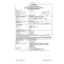
Harman Kardon GPS 500 EMC - CB Certificate ▷ View online
<11006065 001>
Page 46 of 71
TRF No.:IECEN60950_1B
TRF originator: SGS Fimko
F1/RF
0.2
240/50
7.09
0.07
0.07
dto
F1/RF
0.2
240/60
7.08
0.07
0.07
dto
F1/RF
---
264/50
7.11
0.07
0.07
dto
F1/RF
---
264/60
7.11
0.07
0.07
dto
Note(s):
2.1.1.5
TABLE: max. V, A, VA test
P
Voltage (rated)
(V)
Current (rated)
(A)
Voltage (max.)
(V)
Current (max.)
(A)
VA (max.)
(VA)
5.0
1.0
5.11
2.6
4.5x2.6=11.7
Note(s):
2.1.1.7
TABLE: discharge test
N
Condition
τ
calculated
(s)
τ
measured
(s)
t u
→
0V
(s)
Comments
2.2.2
TABLE: Hazardous voltage measurement
P
Max. Voltage
Transformer
Location
V peak
V d.c.
Voltage Limitation
Component
T1
pin 5 - 7
24.4
--
--
Note(s): Supply voltage: 240Vac, 60Hz
2.2.3
TABLE: SEL voltage measurement
N
Location
Voltage measured (V) Comments
Note(s):
2.4.2
TABLE: limited current circuit measurement
P
Location
Voltage
(V)
Current
(mA)
Freq.
(kHz)
Limit
(mA)
Comments
<11006065 001>
Page 47 of 71
TRF No.:IECEN60950_1B
TRF originator: SGS Fimko
C8 secondary pin to earth
0.63
0.32
0.06
0.7
normal
Note(s):
Output measured with a 2 k
Output measured with a 2 k
Ω
non-inductive resistor as load.
Bridging capacitor: C8=100pF
2.5
TABLE: limited power source measurement
P
Limits
Measured
Verdict
According to Table 2B (normal condition), Uoc=5.11V
current (in A)
8
2.6
Pass
apparent power (in VA)
5
×
Uoc
11.7
Pass
According to Table 2B (PC1 pin 1 to pin 2 shorted condition), Uoc=7.06V
current (in A)
8
1.9
Pass
apparent power (in VA)
5
×
Uoc
12.4
Pass
According to Table 2B (PC2 pin 1 to pin 2 shorted condition), Uoc=5.11V
current (in A)
8
2.6
Pass
apparent power (in VA)
5
×
Uoc
11.7
Pass
According to Table 2B (R11 shorted condition), Uoc=7.06V
current (in A)
8
1.9
Pass
apparent power (in VA)
5
×
Uoc
12.4
Pass
According to Table 2B (PC1 pin 3 to pin 4 shorted condition)
current (in A)
8
0
Pass
apparent power (in VA)
5
×
Uoc
0
Pass
According to Table 2B (PC2 pin 3 to pin 4 shorted condition)
current (in A)
8
0
Pass
apparent power (in VA)
5
×
Uoc
0
Pass
Note(s):
2.6.3.4
TABLE: ground continue test
N
Location
Resistance measured (m
Ω
) Comments
Note(s):
2.10.2
Table: working voltage measurement
P
<11006065 001>
Page 48 of 71
TRF No.:IECEN60950_1B
TRF originator: SGS Fimko
Location
RMS voltage (V) Peak voltage (V) Comments
T1 pin1 – pin5
165
356
T1 pin1 – pin7
166
345
T1 pin2 – pin5
201
470
T1 pin2 – pin7
203
475
* Highest working voltage
T1 pin3 – pin5
176
370
T1 pin3 – pin7
176
356
T1 pin4 – pin5
176
370
T1 pin4 – pin7
176
395
PC1 pin1 – pin3
179
370
PC1 pin1 – pin4
179
370
PC1 pin2 – pin3
179
370
PC1 pin2 – pin4
179
370
PC2 pin1 – pin3
179
370
PC2 pin1 – pin4
179
370
PC2 pin2 – pin3
178
365
PC2 pin2 – pin4
178
365
C8 pin1 – pin2
166
345
Note(s):
Supply Voltage: 240V, 60Hz
Supply Voltage: 240V, 60Hz
2.10.3 and
2.10.4
TABLE: clearance and creepage distance measurements
P
Clearance cl and creepage
distance dcr at/of:
Up
(V)
U r.m.s.
(V)
Required cl
(mm)
cl
(mm)
Required
dcr (mm)
dcr
(mm)
Primary component C2 (with
10N) to C8 secondary pin (with
10N)
420
250
4.0
7.0
5.0
7.0
Primary component C2 (with
10N) to outer surface of
enclosure
420
250
4.0
6.0
5.0
6.0
Primary component T1 core to
secondary component D1 (with
10N)
420
250
4.0
5.0
5.0
5.0
Primary traces to secondary
traces
420
250
4.0
↓
5.0
↓
- under PC1/PC2
5.7
5.7
- under C8
5.7
5.7
<11006065 001>
Page 49 of 71
TRF No.:IECEN60950_1B
TRF originator: SGS Fimko
- under T1
475
250
4.2
5.2
5.0
5.2
Traces between Line and
Neutral before the fuse
420
250
1.5
2.5
2.5
2.5
Under fuse
420
250
1.5
6.5
2.5
6.5
Line/Neutral conductor of snap-
fit plug to outer surface
420
250
4.0
5.0
5.0
5.0
Note(s):
1. Operational insulation shorted, see sub-clause 5.3.4.
2. Sleeved component: D7
3. Glued components: C2, D6, LF1
1. Operational insulation shorted, see sub-clause 5.3.4.
2. Sleeved component: D7
3. Glued components: C2, D6, LF1
2.10.5
TABLE: distance through insulation measurements
P
Distance through insulation di at/of:
U r.m.s.
(V)
Test voltage
(V)
Required di
(mm)
di
(mm)
Photocouplers (reinforced insulation)
250
3000
0.4
1)
Enclosure (reinforced insulation)
250
3000
0.4
1.8 min.
1) Refer to appended table 1.5.1 for details.
4.5.1
TABLE: maximum temperatures
P
test voltage (V) :
See below
t1 (
°
C) :
--
t2 (
°
C) :
--
Maximum temperature T of part/at:
T (°C)
allowed
T
max
(°C)
Sample position
Output cable to left
Plug down
Output cable down
Test voltage
90Vac
264Vac
90Vac
264Vac
--
1. Ambient
45.0
45.0
45.0
45.0
--
2. T1 coil
97.5
92.8
98.5
94.8
110
3. T1 core
93.3
89.6
94.3
91.6
110
4. PC1 body
74.9
72.0
75.0
73.1
100
5. PC2 body
84.4
80.9
85.1
82.5
100
6. C1 body
65.7
59.2
66.1
60.3
85
7. NF1 coil
71.4
62.1
72.3
63.6
120
8. PCB near D4
71.2
63.8
72.7
65.9
105
9. PCB near C2
72.9
66.4
74.6
68.6
105
10. PCB near HS of IC1
86.2
78.6
87.2
80.6
105
Click on the first or last page to see other GPS 500 service manuals if exist.

