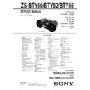
Sony ZS-BTY50 / ZS-BTY52 / ZS-BTY55 Service Manual ▷ View online
ZS-BTY50/BTY52/BTY55
9
2-6. NICKEL BATTERY SUB ASSY (BAT1) (BTY55)
2 Remove the nickel battery sub assy
block in the direction of an arrow.
3 nickel battery sub assy
(BAT1)
BAT1
1 connector
(CN1003)
– Rear bottom side view –
:LUHVHWWLQJ
Note: Stuff wires into the gap.
2-7. JACK LID
– Rear bottom side view –
1 tapping screw
(BV
B2.6)
1 tapping screw
(BV
B2.6)
1 two tapping screws
(BV
B2.6)
2 Remove the jack lid in the
direction of an arrow.
3 jack lid
ZS-BTY50/BTY52/BTY55
10
2-8. CABINET (UPPER) BLOCK
– Rear side view –
2 Lift up the telescopic
antenna.
5 Remove the cabinet (upper) block
in the direction of an arrow.
0 cabinet (upper) block
:LUHVHWWLQJ
:LUHVHWWLQJ
–5HDUERWWRPVLGHYLHZ–
OK
NG
1 two tapping screws
(BV
B2.6)
1 two tapping screws
(BV
B2.6)
1 two tapping screws
(BV
B2.6)
3 two tapping screws
(BV
B2.6)
MAIN board
The wire is caught in the rib.
–5HDUERWWRPVLGHYLHZ–
1 two tapping screws
(BV
B2.6)
1 two tapping screws
(BV
B2.6)
1 two tapping screws
(BV
B2.6)
(BTY50/BTY52)
(BTY55)
4 connector
(CN003)
6 connector
(CN902)
7 flexible flat cable (7P)
(CN803)
8 flexible flat cable (7P)
(CN802)
9 flexible flat cable (14P)
(CN302)
colored line
colored line
Insert is straight to the interior.
Insert is incline
connector
connector
OK
NG
Note 1: When installing the flexible flat cable, ensure the colored line.
No slanting after insertion.
Note 2: CN802 and CN803 have the same size and quantity of a pin.
When installing flexible flat cable (7P), be careful not to mistake.
When installing flexible flat cable (7P), be careful not to mistake.
flexible flat cable
flexible flat cable
MAIN board
TUNER board
ZS-BTY50/BTY52/BTY55
11
2-9. VOL BOARD
–
Bottom side view
–
1 jog (VOL)
3 two tapping screws
(BV
B2.6)
4 VOL board
2 connector
(CN702)
rib
cutting lack
Note: When installing, the position of
rib and cutting lack is set
and
installed.
2-10. Bluetooth MODULE
1 tapping screw
(BV
B2.6)
3 flexible flat cable (14P)
(FFC1)
2 Remove the Bluetooth module
in the direction of an arrow.
–
Rear bottom side view
–
colored line
colored line
Insert is straight to the interior.
Insert is incline
connector
connector
OK
NG
Note 1: When installing the flexible flat cable, ensure the colored line.
No slanting after insertion.
flexible flat cable
flexible flat cable
4 Bluetooth module
Note
2: When replacing Bluetooth module,
please exchange NFC tag
simultaneously.
ZS-BTY50/BTY52/BTY55
12
2-11. LCD BOARD
colored line
colored line
Insert is straight to the interior.
Insert is incline
connector
connector
OK
NG
1 two tapping screws
(BV
B2.6)
4 flexible flat cable (7P) (FFC3)
(CN501)
flexible flat cable (7P) (FFC3)
tape (sub material)
3 tape
(sub
material)
5 two cushions (A)
2 Remove the LCD board block
in the direction of an arrow.
6 LCD board
LCD board
–
Rear bottom side view
–
Note 1: When installing the flexible flat cable, ensure the colored line.
No slanting after insertion.
Note 2: Do not overflow into this portion.
Flexible flat cable (7P) (FFC3) setting
flexible flat cable
flexible flat cable
Click on the first or last page to see other ZS-BTY50 / ZS-BTY52 / ZS-BTY55 service manuals if exist.

