Sharp LC-52LE831E (serv.man5) Service Manual ▷ View online
LC-52/60LE830E,RU/831E,S/833E
4 – 9
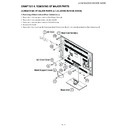
4. Removing of MAIN Unit, POWER/LED Drive Unit, speaker (Sub Woofer), 60” LCD Panel Module Unit.
1. Remove the 5 lock screws and detach the Main PWB Shield .
2. Remove the 2 lock screws and detach the MAIN Unit .
3. Remove the Hexagon screw and detach the Terminal Angle Bottom and Earhe Spring .(Only LC-60LE630E,RU)
4. Remove the 6 lock screws and detach the POWER SUPPLY Unit and Insulator Sheet .
5. Remove the 2 lock screws and detach the Speaker (Sub Woofer) .
6. Remove the 16 lock screws and detach the Center Angle-L , Center Angle-R .
7. Detach the 14 Fixing Metal Angles .
8. Remove the 8 Hooks and detach the 60” LCD Panel Module Unit .
9. Remove the 1 lock screw and detach the ECO-SW .
7 Insulator Sheet
Main PWB Shield
Hook
Hook
Hook
Hook
12
Fixing Metal
Angle
12
Fixing Metal
Angle
12
13
13
13
13
Fixing Metal
Angle
12 Fixing
Metal Angle
12 Fixing
Metal Angle
60" LCD Panel
Module Unit
Module Unit
14
12 Fixing
Metal Angle
12
Fixing
Metal Angle
Metal Angle
9
9
11 Center
Angle-R
10 Center
Angle-L
8
Speaker
(Sub Woofer)
[SB]
6
POWER SUPPLY Unit
5
3
Terminal
Angle Bottom
4
MAIN Unit
1
15
2
17
16
20 Earth Spring
18
19 ECO-SW
[AS]
LC-52/60LE830E,RU/831E,S/833E
4 – 10
5. Removing of R/C, Operation Unit, ICON Unit, 3D IR Emitter Unit, Touch Sensor Unit.
1. Remove the 1 lock screw and detach the ICON Unit .
2. Detach the R/C, Operation Unit .
3. Detach the 3D IR Emitter Unit .
4. Detach the Touch Sensor Unit .
NOTE: The Touch Sensor unit reuse will be impossible, once it is stuck on front cabinet and exfoliates.
Front Cabinet Ass'y
[TK] [RA]
Touch Sensor Unit
2
[IR]
[RA]
[CI]
3
ICON
Unit
Unit
5
6
3D IR Emitter
Unit
Unit
4 R/C,
Operation
Unit
Unit
LC-52/60LE830E,RU/831E,S/833E
4 – 11
[3] The location putting on the heat measure sheet
1. MAIN PWB Unit
The object to cool.
(The sheet is put on the back of the
board.)
The guide line is impressed on the backlight
chassis
PSPAZC702WJKZ
Main PWB Unit
(DUNTKF733WE**)
LC-52/60LE830E,RU/831E,S/833E
4 – 12
2. LCD Control Unit
The IC to cool
LCD control unit
(RUNTK4909TP**)
Please put [PSPAZC062WJKZ] on the IC
Click on the first or last page to see other LC-52LE831E (serv.man5) service manuals if exist.

