Sharp LC-30HV2E (serv.man19) User Manual / Operation Manual ▷ View online
42
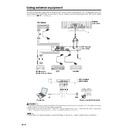
Using external equipment
Option
MENU
Input Select
Input3
[COMPONENT]
Y/C
RGB
COMPONENT
AV
P
B
(C
B
)
COMPONENT
P
R
(C
R
)
Y
R - AUDIO - L
INPUT 3
INPUT 2
INPUT 1
RS-232C
DISPLAY OUTPUT1
DISPLAY OUTPUT2
AC INPUT
220–240V
220–240V
AV OUTPUT
S-VIDEO
VIDEO
AVC System (rear view)
DVD player
Component cable (commercially available)
SCART cable
(commercially available)
(commercially available)
INPUT SOURCE
TV
INPUT1
INPUT2
INPUT3
INPUT4
PC
When using component cable,
select “COMPONENT” for “Input
Select” in the menu.
select “COMPONENT” for “Input
Select” in the menu.
Watching a DVD image
Connecting a DVD player
You can use the INPUT 3 terminal when connecting to a DVD player and other audiovisual equipment.
Displaying a DVD image
When connecting to the INPUT 3 terminal, select “Input
3” on “Input Select” in the menu to set the correct input
signal type. (See page 49.)
3” on “Input Select” in the menu to set the correct input
signal type. (See page 49.)
The setting is stored and can be selected on the
“INPUT SOURCE” menu.
“INPUT SOURCE” menu.
To watch a DVD image, select “INPUT3” from “INPUT
SOURCE” menu using b on the remote control unit
or INPUT on the Display. (See page 49.)
SOURCE” menu using b on the remote control unit
or INPUT on the Display. (See page 49.)
A
• Each time b is pressed, the input source toggles.
• If the DVD image does not come in clearly, you may need
• If the DVD image does not come in clearly, you may need
to change the input signal type setting on the “Input Select”
menu.
menu.
• Refer to your DVD player operation manual for the signal
type.
43
Using external equipment
AVC System (front view)
Game console/Camcorder
Composite video cables
(commercially available)
(commercially available)
S-video cable
(commercially available)
(commercially available)
INPUT SOURCE
TV
INPUT1
INPUT2
INPUT3
INPUT4
PC
Enjoying a game console and viewing camcorder images
Connecting a game console or camcorder
A game console, camcorder and some other audiovisual equipment are conveniently connected using the
INPUT 4 terminals.
INPUT 4 terminals.
A
• The S-video terminal has priority over the video terminals.
Displaying an image of the game player and
camcorder
camcorder
When connecting to the INPUT 4 terminals, select
“INPUT4”.
“INPUT4”.
You only need to select the input source on the “INPUT
SOURCE” menu.
SOURCE” menu.
To connect a game console or view a camcorder, select
“INPUT4” from the “INPUT SOURCE” menu using b
on the remote control unit or INPUT on the Display.
(See page 49.)
“INPUT4” from the “INPUT SOURCE” menu using b
on the remote control unit or INPUT on the Display.
(See page 49.)
A
• Each time b is pressed, the input source toggles.
44
Using external equipment
RGB cable
(commercially available)
(commercially available)
AVC System (front view)
ø 3.5 mm stereo minijack cable
(commercially available)
(commercially available)
Computer
15
14
13
12
9
11
10
8
7
6
5
4
3
2
1
INPUT SOURCE
TV
INPUT1
INPUT2
INPUT3
INPUT4
PC
Pin No.
Signal name
Pin No.
Signal name
Pin No.
Signal name
1
R
6
GND (Ground)
q
Not connected
2
G
7
GND (Ground)
w
SDA
3
B
8
GND (Ground)
e
HD
4
Not connected
9
+5V
r
VD
5
CSYNC
0
GND (Ground)
t
SCL
Viewing an image from a computer
Connecting a computer
Use the PC terminals to connect a computer.
A
• The PC input terminals are DDC1/2B-compatible.
• Refer to page 63 for a list of computer signals compatible with the System.
• Refer to page 63 for a list of computer signals compatible with the System.
Signal names for 15-pin mini D-sub connecter
A
• Macintosh adaptor may be required for use for some Macintosh computers.
• Macintosh adaptor may be required for use for some Macintosh computers.
Displaying an image from a computer
When connecting to a computer, the correct input
signal type is automatically detected. (See page 49.)
If the computer image does not come in clearly, you
may need to set the Auto Sync. adjustment on the “Auto
Sync.” in the menu. (See page 48.)
signal type is automatically detected. (See page 49.)
If the computer image does not come in clearly, you
may need to set the Auto Sync. adjustment on the “Auto
Sync.” in the menu. (See page 48.)
You only need to select the input source on the “INPUT
SOURCE” menu.
SOURCE” menu.
To view an image from a computer, select “PC” from
the “INPUT SOURCE” menu using b on the remote
control unit or INPUT on the Display. (See page 49.)
the “INPUT SOURCE” menu using b on the remote
control unit or INPUT on the Display. (See page 49.)
A
• Each time b is pressed, the input source toggles.
45
Using external equipment
Removing the speakers
This unit has detachable type speakers.
Before attaching/detaching speakers
• Before performing work make sure to turn off the System.
• Before performing work spread cushioning over a flat surface to lay the Display on. This will prevent it from
• Before performing work spread cushioning over a flat surface to lay the Display on. This will prevent it from
being damaged.
L
• The speaker terminals on the Display is only for the attached speakers. Do not connect any third party plug or speaker to
the terminal.
• Insert the speaker plug completely into the terminal.
• Do not handle or move the display by the speakers.
• Do not handle or move the display by the speakers.
A
• Perform the same steps for both left and right speakers.
• To attach the speakers, perform the above steps in reverse order.
• To attach the speakers, perform the above steps in reverse order.
Unfasten the screws used to
secure the speakers in place.
secure the speakers in place.
Take hold of the speaker and
slowly slide it sideways.
(The speaker plug is still
inserted, so make sure not to
pull the speaker too far.)
slowly slide it sideways.
(The speaker plug is still
inserted, so make sure not to
pull the speaker too far.)
Remove the speaker plug from
the terminal on the Display.
(Do not remove the plug by
pulling the cord.)
Now the speaker can be
detached from the display.
the terminal on the Display.
(Do not remove the plug by
pulling the cord.)
Now the speaker can be
detached from the display.
1
2
3
Speaker
plug
plug
Display

