Sharp LC-15L1E (serv.man8) Service Manual ▷ View online
26
LC-15L1E
YES
NO
YES
YES
YES
YES
NO
YES
YES
NO
NO
NO
NO
YES
NO
NO
NO
YES
NO
NO
YES
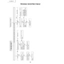
IC1100 failure
NO
NO
YES
No sound
YES
YES
IC704 failure
IC1500 failure
NO
YES
NO
YES
YES
YES
No picture
NO
NO
NO
YES
Is DC voltage normal at each of the
following pins?
Pin (8) of IC1501
→
+8.0V
Pins (1), (2), (14) and (24) of
IC1500
→
+3.3V
Is output signal waveform at pins
(19) and (20) of IC1500 similar to
that of the input signal supplied to
Smart Link transmitter?
Pin (19)
→
L, Pin (20)
→
R
Are pins (7) and (8) of IC1500 at HI
(+3.3V) level?
Is control signal normal at each of
pins (9), (10) and (11) of IC1500?
Is signal waveform normal at pin
(15) of IC1500?
Check each IC
and the
peripheries of
L1500 and
L1501.
Check IC1501
periphery.
Check for
connector
damage or cable
disconnection.
Is output signal waveform available at
pins (1), (3) and (5) of CN1?
Is output signal waveform available at
pins (26), (27) and (31) of IC1100?
Is normal +5.0V available at pin (5) of
IC1300 and pin (8) of IC1302?
Are the waveforms normal at pins (2), (5)
and (6) of IC1302?
Does TP_PWM show normal waveform?
IC1501 failure
Check the
peripheries of
L1101-L1103.
IC1000 failure
(Not serviceable)
Check for connector
damage or cable
disconnection.
IC704 failure
Q701 failure
IC1000 failure
(Not serviceable)
Check the periphery
of each IC.
Check the
peripheries of
IC1302 and XC1301.
Are the waveforms of clock signal
at pin (44) and data signal at pin
(41) of IC1100 normal?
Remote controller does not work.
* Pictures and sounds are
produced.
Perform the following checks by
actually operating the remote
controller for a video source.
Is there an output of data signal
waveform at pin (12) of CN1?
Is there an output of data signal
waveform at pin (19) of IC704?
Is normal +8.0V
available at pins
(3) and (5) of
IC1501?
Check for
connector
damage or
cable
Q1501 and
Q1502 failure
IC704 failure
Q1500 failure
Is output signal
waveform at pins (1)
and (7) of IC1501
similar to the waveform
mentioned on the left?
Pin (1)
→
R, Pin (7)
→
L
Is output signal
mentioned above
available at pins (7) and
(9) of CN2?
Pin (7)
→
R, Pin (9)
→
L
Are base terminals of
Q1501 and Q1502 at
LOW (0V) level?
Is base terminal of
Q1500 at HI (+3.3V)
level?
IC1000 failure
(Not serviceable)
IC1000 failure
(Not serviceable)
»
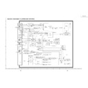
TV receiver side fault-finding flowchart with normal link
~
Perform the following checks while maintaining the link and feeding the signals to Wireless Center.
Reference waveform: VIDEO
Reference waveform: VIDEO
→
Colour bar
AUDIO
→
1KHz SIN wave
27
LC-15L1E
»
Wireless Center (TX) side fault-finding flowchart with no link
NO
NO
NO
NO
NG
NO
NO
NO
NO
NO
Go to the
step A.
9
.
OK
YES
NO
Replace
the cable.
YES
YES
OK
YES
OK
YES
Check the microcomputer operation using terminal software.
A. No display
YES
No link
YES
YES
OK
YES
OK
2
Is normal +3.3V output available
at pin (4) of IC5906?
C. MPEG setup OK is not
displayed.
1
Is normal +1.5V available at
both ends of L6000, and
+3.3V at both ends of L6001?
D. No display after APOLL2
startup
1
Check IC6701 periphery.
3
Go to the step E.
2
.
E. All displays are normal.
3
Replacement of UNT6700
did not help recover normal
operation.
4
Check the peripheries of
pins (40)-(43) of IC5704.
5
Check CN5200 peripheries.
1
Using a spectrum analyzer
or the like, check that output
signal has RF waveform.
2
Check that the cable
connecting CN5200 and
UNT6700 has no
interference or damage.
2
Is normal +3.3V available at
each of the following pins of
IC6701?
(1), (8), (31), (37), (44), (54),
(67), (73), (80), (90), (103),
(109), (116), (126), (133) and
(139)
3
Is output signal waveform normal
at pin (13) of IC5704?
4
Is normal +3.3V output available
at pin (4) of IC5706?
6
Check IC5704 and Q5705
peripheries.
7
Check IC5902 periphery.
8
Is normal +1.5V available at
TP5902?
9
Is normal +3.3V available at
TP5900?
0
Is normal +5.0V output available
at pin (4) of IC5907?
q
Check IC6500 periphery.
IC5704 failure
1
Is normal +9V available at pins
(1)-(3) of CN5002?
Check for connector
damage or cable
disconnection.
Check IC5906
periphery.
Check L6000
and L6001.
Not serviceable
Check FL5701
periphery.
Check IC5706
periphery.
Check Q5904
periphery.
Check Q5902
periphery.
Check IC6501 and
Q5903 peripheries.
Go to the step B.
1
.
28
LC-15L1E
»
TV receiver (RX) side fault-finding flowchart with no link
Not serviceable
IC1704 failure
OK
OK
OK
A. No display
YES
YES
YES
YES
NO
NO
NO
NO
NO
YES
NO
NO
NO
NO
NO
NO
YES
YES
YES
YES
YES
YES
OK
No link
Check the microcomputer operation using terminal software.
OK
OK
1
Is normal +9V available at pins
(1)-(3) of CN2?
B. No second time Version display
C. MPEG setup OK is not
displayed.
D. No display after APOLL2
startup
E. All displays are normal.
1
Using a spectrum analyzer
or the like, check that output
signal has RF waveform.
2
Check that the cable
connecting CN200 and
UNT1700 has no
interference or damage.
3
Replacement of UNT1700
did not help recover normal
operation?.
4
Check pins (40)-(43) of
IC704 and the peripheries.
5
Check CN200 and the
peripheries.
2
Is normal +3.3V available at each
of the following pins of IC1701?
(1), (8), (31), (37), (44), (54),
(67), (73), (80), (90), (103),
(109), (116), (126), (133) and
(139)
1
Check IC1701 and the periphery.
3
Go to the step E.
2
.
1
Is normal +1.5V available at
both ends of L6000, and
+3.3V at both ends of L6001?
3
Is signal waveform normal at pin
(44) of IC1100?
1
Check IC1100 and the periphery.
4
Check the following connections.
Between pin (23) of IC1100 and
pin (21) of IC704
Between pin (24) of IC1100 and
pin (23) of IC704
2
Is output normal at the following
pins of IC1100?
(1), (11), (20), (28) and (30): +3.3V
2
Is normal +3.3V output
available at pin (4) of IC906?
3
Is output signal waveform
normal at pin (13) of IC704?
4
Is normal +3.3V output
available at pin (4) of IC706?
6
Check IC704, Q705 and their
peripheries.
7
Check IC902 and the periphery.
8
Is normal +1.5V available at
TP902?
9
Is normal +3.3V available at
TP900?
0
Is normal +5.0V output
available at pin (4) of IC907?
q
Check IC1500 periphery.
Check for
connector
damage or cable
disconnection.
Check IC906
periphery.
Go to the step
A.
9
.
Go to the step
A.
8
.
Check L6000
and L6001.
Go to the
step A.
9
.
Replace the
cable.
Check FL701
periphery.
Check IC706
periphery.
Check Q904
periphery.
Check Q902
periphery.
Check IC1501
and Q903
peripheries. Go
to the step B.
1
.

