Sharp LC-15L1E (serv.man6) Service Manual ▷ View online
9
LC-15L1E
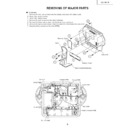
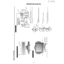
REMOVING OF MAJOR PARTS
Ë
TV section
1. Remove the four lock screws from the stand, and detach the table stand.
2. Detach the terminal cover.
3. Detach the battery cover.
4. Remove the lock screw from the terminal block.
5. Remove the three lock screws from the battery compartment.
6. Remove the twelve lock screws from the cabinet B, and detach the cabinet B.
7. Disconnect the connectors from the PWBs.
2. Detach the terminal cover.
3. Detach the battery cover.
4. Remove the lock screw from the terminal block.
5. Remove the three lock screws from the battery compartment.
6. Remove the twelve lock screws from the cabinet B, and detach the cabinet B.
7. Disconnect the connectors from the PWBs.
6
6
2
1
3
1
Battery Cover
Table Stand(Detachable)
Cabinet B
Terminal Cover
Stand
6
5
6
4
P4051
P2001
P3204
P3201
P2004
CN2
CN2
CN1
CN3
P6504
P3202
P4051
P3203
SC1204
SC1203
SC1202
F3802
CN3
CN2
CN1
P4051
P2002
P3205
F3801
P4001
P9001
P9003
P9002
P2003
CN1
P3802
P9901
F3803
7
7
7
7
7
7
7
7
7
7
7
7
7
7
7
7
7
Battery Connector PWB
Inverter PWB
Charger PWB
Operation PWB
Cabinet A
R/C, LED PWB
SS(RX) PWB
DC Jack PWB
Main PWB
10
LC-15L1E
»
Precautions in reassembling the SS unit
1. Do not touch by hand the antennas that are on the ANT PWBs to be coupled to the SS unit. Place these
PWBs in position with enough care to keep the antennas in the original shape.
(If by any chance the antenna gets bent or deformed, do not reshape it by hand, nor use the PWB again.
Otherwise communication failure may result.)
2. Insert the connectors of the ANT PWBs from just above tightly to their counterparts on the SS unit. (Do not
insert them slantwise.)
To disconnect the antenna connectors from the SS unit, hold and pull them out vertically. Do not hold the
cables to disconnect. (Otherwise the cables may get broken or the connectors damaged.)
3. Handling the SS unit RF cable
With the SS unit fit in position, dress and secure the RF cable, free of extra load, in its original route.
8. Remove the two lock screws from the operation panel (top cover), and detach the operation panel (top cover)
assembly.
9. Remove the two lock screws from the DC jack PWB and the lock screw from the angle. Detach the DC jack
PWB and the angle.
10. Remove the two lock screws from the R/C, LED PWB, and detach the R/C, LED PWB.
11. Remove the two lock screws from the battery connector PWB, and detach the battery connector PWB.
12. Remove the lock screws one each from the SS (RX) antenna PWBs, and detach the SS (RX) antenna PWBs.
13. Remove the lock screws two each from the speakers, and detach the speakers.
11. Remove the two lock screws from the battery connector PWB, and detach the battery connector PWB.
12. Remove the lock screws one each from the SS (RX) antenna PWBs, and detach the SS (RX) antenna PWBs.
13. Remove the lock screws two each from the speakers, and detach the speakers.
9
10
11
13
13
12
12
8
Battery Connector PWB
Speaker (L)
Speaker (R)
Operation PWB
R/C, LED PWB
Angle
SS(RX) Antenna PWB
SS(RX) Antenna PWB
Top cover
DC Jack PWB
11
LC-15L1E
14. Remove the two lock screws from the inverter PWB, and detach the inverter PWB.
15. Remove the two lock screws from the charger PWB, and detach the charger PWB.
16. Remove the two lock screws from the SS (RX) PWB, and detach the SS (RX) PWB.
17. Remove the five lock screws from the main PWB, and detach the main PWB.
18. Remove the two lock screws from the chassis frame, and detach the chassis frame.
19. Remove the lock screw from the LCD panel unit, and detach the LCD panel unit.
17
19
18
18
14
15
16
17
LCD Panel Unit
Inverter PWB
Chassis Frame
Charger PWB
SS(RX) PWB
Main PWB
12
LC-15L1E
»
Precautions in handling the LCD panel
1. Handle the panel in a clean room (at humidities of over 50%).
2. Be sure to wear a wrist band to handle the panel.
3. Be careful not to drop or vibrate the panel.
4. Use an ionizer (within 30 cm).
2. Be sure to wear a wrist band to handle the panel.
3. Be careful not to drop or vibrate the panel.
4. Use an ionizer (within 30 cm).
20. Remove the two lock screws from the LCD panel unit, and detach the LCD panel unit.
21. Detach the diffusion sheet, prism sheet and reflection/deflection sheet.
22. Detach the four reflectors (top, bottom, right and left).
23. Detach the two reflection sheets (covers).
24. Detach the light guide plate.
25. Detach the fluorescent lamp.
26. Detach the two reflection sheets.
21. Detach the diffusion sheet, prism sheet and reflection/deflection sheet.
22. Detach the four reflectors (top, bottom, right and left).
23. Detach the two reflection sheets (covers).
24. Detach the light guide plate.
25. Detach the fluorescent lamp.
26. Detach the two reflection sheets.
21
25
23
24
26
22
Lamp Unit
(KLMP-0122CEZZ)
(KLMP-0122CEZZ)
Reflection Sheet (Cover)
(PSHEP0307CEZZ)
(PSHEP0307CEZZ)
Light Guide Plate
(PGiDM0070CEZZ)
(PGiDM0070CEZZ)
Reflection Sheet-1
(PSHEP0284CEZZ)
(PSHEP0284CEZZ)
Reflection Sheet-2
(PSHEP0285CEZZ)
(PSHEP0285CEZZ)
Diffusion Sheet
(PSHEP0283CEZZ)
(PSHEP0283CEZZ)
Prism Sheet
(PSHEA141WJZZ)
(PSHEA141WJZZ)
Reflection/Deflection Sheet
(PSHEP0281CEZZ)
(PSHEP0281CEZZ)
Reflection Mirror
22 Reflection Mirror
Back Shield
20
20
LCD Panel Unit
Display

