Sharp XV-Z200E (serv.man36) User Manual / Operation Manual ▷ View online
Appendix
-67
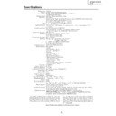
Specifications
Product type
Model
Video system
Display method
DLP panel
Lens
Projection lamp
Video input signal
S-video input signal
Component input signal
(INPUT 1)
Component input signal
(INPUT 2)
Horizontal resolution
RGB input signal
Pixel clock
Vertical frequency
Horizontal frequency
Computer control signal
Rated voltage
Input current
Rated frequency
Power consumption
Heat dissipation
Operating temperature
Storage temperature
Cabinet
I/R carrier frequency
Dimensions (approx.)
Weight (approx.)
Supplied accessories
Replacement parts
Projector
XV-Z200E
PAL/PAL 60/PAL-M/PAL-N/SECAM/NTSC 3.58/NTSC 4.43
DTV 480
XV-Z200E
PAL/PAL 60/PAL-M/PAL-N/SECAM/NTSC 3.58/NTSC 4.43
DTV 480
I
/480P/720P/1080
I
DLP chip, RGB optical shutter method
Panel size: 0.6
Panel size: 0.6
⬙
Display method: Single Panel Digital Micromirror Device (DMD™) by Texas Instruments
Drive method: Digital Light Processing (DLP™)
No. of dots: 589,824 dots (1,024 [H]
Drive method: Digital Light Processing (DLP™)
No. of dots: 589,824 dots (1,024 [H]
⳯ 576 [V])
1–1.2
⳯ zoom lens, F1.75–2.04 f=28.0–33.5 mm
210 W/168 W SHP lamp
RCA Connector: VIDEO (INPUT 4), composite video, 1.0 Vp-p, sync negative, 75
RCA Connector: VIDEO (INPUT 4), composite video, 1.0 Vp-p, sync negative, 75
Ω
terminated
4-pin Mini DIN connector (INPUT 3)
Y (luminance signal): 1.0 Vp-p, sync negative, 75
4-pin Mini DIN connector (INPUT 3)
Y (luminance signal): 1.0 Vp-p, sync negative, 75
Ω terminated
C (chrominance signal): Burst 0.286 Vp-p, 75
Ω terminated
RCA Connector
Y: 1.0 Vp-p, sync negative, 75
Y: 1.0 Vp-p, sync negative, 75
Ω terminated
P
B
: 0.7 Vp-p, 75
Ω terminated
P
R
: 0.7 Vp-p, 75
Ω terminated
29-pin connector
DVI input signal: Digital 250–1,000 mV 50
DVI input signal: Digital 250–1,000 mV 50
Ω
Analog 0.7 Vp-p 75
Ω
Y: 1.0 Vp-p, sync negative, 75
Ω terminated
P
B
: 0.7 Vp-p, 75
Ω terminated
P
R
: 0.7 Vp-p, 75
Ω terminated
520 TV lines (NTSC 3.58 input)
DVI-I terminal
<Digital>
Input impedance
DVI-I terminal
<Digital>
Input impedance
50
Ω
Input level
250-1000 mV
<Analog>
Input impedance
Input impedance
75
Ω
Input level
0.7 Vp-p
<Synchronization signal>
• Separate sync/Composite sync
Input level
TTL level
Input impedance
1 K
Ω
• Green on sync
Input level (Synchronizing input)
0.286 Vp-p
Input impedance
75
Ω
12–80 MHz
43–75 Hz
15–70 kHz
9-pin D-sub connector (RS-232C Port)
AC 100–240 V
3.2 A
50/60 Hz
285 W
1,070 BTU/hour
43–75 Hz
15–70 kHz
9-pin D-sub connector (RS-232C Port)
AC 100–240 V
3.2 A
50/60 Hz
285 W
1,070 BTU/hour
Ⳮ5°C to Ⳮ35°C
ⳮ20°C to Ⳮ60°C
Plastic
38 kHz
368 (W)
38 kHz
368 (W)
⳯ 153.8 (H) ⳯ 327 (D) mm (including swivel stand)
368 (W)
⳯ 118 (H) ⳯ 327 (D) mm (main body only)
4.6 kg (including swivel stand)
4.1 kg (main body only)
Remote control, Two AA size batteries, Power cord, 21 pin RCA conversion adaptor,
Video cable, Terminal cover, Screws for terminal cover, Lens cap (attached on the
body), Operation manual
Lamp unit (Lamp/cage module) (BQC-XVZ200++1), Remote control
(RRMCGA218WJSA), AA size batteries, Power cord for Europe except U.K.
(QACCV4002CEZZ), Power cord for U.K., Hong Kong and Singapore
(QACCBA012WJPZ), Power cord for Australia and New Zealand (QACCLA018WJPZ),
21 pin RCA conversion adaptor (QSOCZ0361CEZZ), Video cable (QCNWGA001WJZZ),
Terminal cover (GCOVAA116WJKB), Screws for terminal cover (XBBSN40P10000), Lens
cap (CCAPHA004WJ01), Operation manuals; for European 7 languages (TINS-
B007WJZZ) / for Chinese, Korean and Arabic (TINS-B008WJZZ)
Specifications are subject to change without notice.
This SHARP projector uses a DMD chip. This very sophisticated chip contains 589,824 pixels. As with any high
technology electronic equipment such as large screen TVs, video systems and video cameras, there are certain
acceptable tolerances that the equipment must conform to.
technology electronic equipment such as large screen TVs, video systems and video cameras, there are certain
acceptable tolerances that the equipment must conform to.
XV_Z200E_E_p67_70.p65
03.10.30, 13:15PM
67
-68
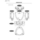
327
153.8
118
368
Front View
Bottom View
Side View
Top View
Side View
Rear View
Dimensions
Units: mm
XV_Z200E_E_p67_70.p65
03.10.30, 13:15PM
68
Appendix
-69
Glossary
Aspect Ratio
Width and height ratio of an image. The normal
aspect ratio of a computer and video image is 4:3.
There are also wide images with an aspect ratio
of 16:9 and 21:9.
aspect ratio of a computer and video image is 4:3.
There are also wide images with an aspect ratio
of 16:9 and 21:9.
Auto Sync
Optimizes projected computer images by auto-
matically adjusting certain characteristics.
matically adjusting certain characteristics.
Background
Initial setting image projected when no signal is
being output.
being output.
Clock
Clock adjustment is used to adjust vertical noise
when clock level is incorrect.
when clock level is incorrect.
CLR Temp (Colour temperature)
Function that can be used to adjust the colour tem-
perature to suit the type of image input to the pro-
jector. Decrease the colour temperature to create
warmer, reddish images for natural flesh tones,
or increase to create cooler, bluish images for a
brighter picture.
perature to suit the type of image input to the pro-
jector. Decrease the colour temperature to create
warmer, reddish images for natural flesh tones,
or increase to create cooler, bluish images for a
brighter picture.
Composite sync
Signal combining horizontal and vertical sync
pulses.
pulses.
Digital keystone correction
Function to digitally correct a distorted image when
the projector is set up at an angle, smoothes out
jaggies on keystone images and compresses the
image not only horizontally but vertically keeping
the 16 : 9 aspect ratio.
the projector is set up at an angle, smoothes out
jaggies on keystone images and compresses the
image not only horizontally but vertically keeping
the 16 : 9 aspect ratio.
DVI (Digital Visual Interface)
Display digital interface that also supports analog
interfaces.
interfaces.
Gamma
Image quality enhancement function that offers a
richer image by brightening the darker portions of
the image without altering the brightness of the
brighter portions. You can select from four differ-
ent modes: Standard, Cinema 1, Cinema 2 and
Cinema 3.
richer image by brightening the darker portions of
the image without altering the brightness of the
brighter portions. You can select from four differ-
ent modes: Standard, Cinema 1, Cinema 2 and
Cinema 3.
Intelligent compression and expansion
High quality resizing of lower and higher resolu-
tion images to fit the projector’s native resolution.
tion images to fit the projector’s native resolution.
Phase
Phase shift is a timing shift between isomorphic
signals with the same resolution. When phase level
is incorrect, the projected image typically displays
horizontal flicker.
signals with the same resolution. When phase level
is incorrect, the projected image typically displays
horizontal flicker.
Resize
Allows you to modify or customize the picture dis-
play mode to enhance the input image. You can
select from four different modes: SIDE BAR,
SMART STRETCH, CINEMA ZOOM and
STRETCH.
play mode to enhance the input image. You can
select from four different modes: SIDE BAR,
SMART STRETCH, CINEMA ZOOM and
STRETCH.
RS-232C
Function to control the projector from the com-
puter by using the RS-232C ports on the projec-
tor and computer.
puter by using the RS-232C ports on the projec-
tor and computer.
Stretch
Mode that stretches the 4:3 image horizontally to
display it on the wide screen.
display it on the wide screen.
Sync on green
Video signal mode of a computer which overlaps
horizontal and vertical sync signal to green colour
signal pin.
horizontal and vertical sync signal to green colour
signal pin.
XV_Z200E_E_p67_70.p65
03.10.30, 13:15PM
69
-70
Index
A
AC socket ............................................................. 14
Adjusting the Picture ............................................ 44
ADJUSTMENT buttons ........................................ 39
Aspect ratio .......................................................... 35
Automatic power shut-off function ........................ 54
Auto sync adjustment ........................................... 50
AUTO SYNC button ............................................. 50
B
Background .......................................................... 53
C
Ceiling-mount ....................................................... 28
Ceiling+Rear ........................................................ 56
Clock .................................................................... 48
COMPONENT terminals ...................................... 17
Ceiling+Rear ........................................................ 56
Clock .................................................................... 48
COMPONENT terminals ...................................... 17
D
DIGITAL INPUT terminal ...................................... 20
DVI ....................................................................... 20
DVI ....................................................................... 20
E
Eco mode ............................................................. 53
ENTER button ...................................................... 39
Exhaust ventilative hole ......................................... 6
ENTER button ...................................................... 39
Exhaust ventilative hole ......................................... 6
F
Focus ring ............................................................ 25
FREEZE button .................................................... 35
FREEZE button .................................................... 35
I
INPUT buttons ...................................................... 31
K
Kensington Lock .................................................. 63
KEYSTONE button ............................................... 33
KEYSTONE button ............................................... 33
L
LAMP indicator ..................................................... 58
Lens shift .............................................................. 25
Lens shift .............................................................. 25
M
MENU button ........................................................ 38
O
ON button ............................................................. 30
On-screen display ................................................ 51
On-screen display language ................................ 31
On-screen display ................................................ 51
On-screen display language ................................ 31
P
Phase ................................................................... 48
Power cord ........................................................... 14
POWER indicator ................................................. 30
Power cord ........................................................... 14
POWER indicator ................................................. 30
R
Rear projection ..................................................... 28
Remote control ..................................................... 10
Remote control sensor ......................................... 11
Remote control signal transmitter ........................ 10
RESIZE button ..................................................... 35
RS-232C terminal ................................................ 23
S
STANDBY button ................................................. 32
STRETCH ............................................................ 36
S-VIDEO INPUT terminal ..................................... 15
Sync on green ...................................................... 66
STRETCH ............................................................ 36
S-VIDEO INPUT terminal ..................................... 15
Sync on green ...................................................... 66
T
TEMPERATURE WARNING indicator ................. 58
U
UNDO button ........................................................ 39
V
VIDEO INPUT terminal ........................................ 16
Video System ....................................................... 52
Video System ....................................................... 52
Z
Zoom knob ........................................................... 25
XV_Z200E_E_p67_70.p65
03.10.30, 13:15PM
70

