Sharp XG-PH70X (serv.man3) Service Manual ▷ View online
XG-PH70X/XG-PH70X-N
3 – 5
[4] SERVICE MODE
1. How to enter Service Mode
Select the group “Option2” by user menu and then select “service Mode”.
Enter the password “9303”
2. How to adjust in service mode
– Select the group to adjust with the DOWN key or the UP key,
and enter the adjustment item with the ENTER key on the remote control or key pad.
– Select the adjustment item with the DOWN key or the UP key.
– Use the LEFT key or the RIGHT key for adjustment.
– To return from the adjustment item to the adjustment group, use the UNDO key or the MENU key.
NOTE: – In service mode, user adjustment value will be changed to default value (Picture/CMS).
When you exit from service mode, adjustment value will change to user adjustment value.
– In service mode, the following functions will be canceled.
AV mute / sound mute / freeze / enlarge / PinP
* "standby" button on a remote controller and a operation pad is invalid in the service mode.
If you would like to turn off the power, please exit from service mode.
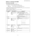
3. Adjustment of white balance
• Adjustment of RGB PC
1. Feed a RGB PC signal to input1
white balance
2. Select the group "DLP"
PH70X will change to input1/RGB mode automatically
PH70X will change to input1/RGB mode automatically
group
Subject
initial value
effective range
adjustment
source/mode
DLP
R1-BLK
0
±20
brightness of red
INPUT1 / RGB
R1-GAIN
0
±20
contrast of red
INPUT1 / RGB
G1-BLK
0
±20
brightness of green
INPUT1 / RGB
G1-GAIN
0
±20
contrast of green
INPUT1 / RGB
B1-BLK
0
±20
brightness of blue
INPUT1 / RGB
B1-GAIN
0
±20
contrast of blue
INPUT1 / RGB
• Adjustment of video
1. Feed a video signal
white balance
2. Select the group "DLPV"
PH70X will change to input4 mode automatically
PH70X will change to input4 mode automatically
group
Subject
initial value
effective range
adjustment
source/mode
DLPV
V-R1-BLK
0
±20
brightness of red
INPUT4 / video
V-R1-GAIN
0
±20
contrast of red
INPUT4 / video
V-G1-BLK
0
±20
brightness of green
INPUT4 / video
V-G1-GAIN
0
±20
contrast of green
INPUT4 / video
V-B1-BLK
0
±20
brightness of blue
INPUT4 / video
V-B1-GAIN
0
±20
contrast of blue
INPUT4 / video
• Adjustment of DTV
1. Feed a component signal to input1
white balance
2. Select the group "DLPV"
PH70X will change to input1/component mode automatically
PH70X will change to input1/component mode automatically
group
Subject
initial value
effective range
adjustment
source/mode
DLPV
C-R1-GAIN
0
±20
contrast of red
INPUT1 / component
C-G1-GAIN
0
±20
contrast of green
INPUT1 / component
C-B1-GAIN
0
±20
contrast of blue
INPUT1 / component
(memo)
The adjustment value of the brightness is common to video.
XG-PH70X/XG-PH70X-N
3 – 6
4. Adjustment of video
5. Others
6. Initialization of adjustment value
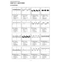
7. Internal test pattern
8. Firmware version
1. Feed a video signal
2. Select the group "VIDEO"
PH70X will change to input4 mode automatically
2. Select the group "VIDEO"
PH70X will change to input4 mode automatically
group
Subject
initial value
effective range
adjustment
source/mode
adjustment of VIDEO
VIDEO
PICTURE
0
±60
contrast
INPUT4 / video
picture
BRIGHT
0
±60
brightness
INPUT4 / video
adjustment of VIDEO
TINT
0
±120
tint (effected in NTSC only)
INPUT4 / video
color
N-COLOR
0
±120
color saturation
INPUT4 / video
setting of VIDEO gain control
AGC-CNT
0-1
auto gain control
INPUT4 / video
0 : AGC On
1 : AGC Off
1 : AGC Off
adjustment of delay
DLY
0
±5
INPUT4 / video
between chroma and luminance
adjustment of VIDEO
horizontal position
adjustment of VIDEO
horizontal position
H-CENTER
0
±10
INPUT4 / video
adjustment of VIDEO
low pass filter
low pass filter
FILTER
0
±3
filter gain
INPUT4 / video
group
Subject
initial value
effective range
adjustment
source/mode
VIDEO
COMP-FILTER
0
0-1
0 : filter off, 1 : filter on
INPUT1 / component
switch of component
low pass filter
low pass filter
switch of RGB
low pass filter
low pass filter
RGB-FILTER
0
0-1
0 : filter off, 1 : filter on
INPUT1 / RGB
switch of audio delay
of internal speaker
of internal speaker
A-DELAY
0
0-1
0 : delay on, 1 : delay off
INPUT4 / video
RESET
- Select this item and push ENTER key.
Value inside each item of "DLP", "DLPV" and "VIDEO" is returned to the initial value with RESET.
group
Subject
initial value
effective range
signal
PATTERN
RGB
1
1-8
raster signal
RGB[50]
1
1-8
50% raster signal
CROSS
1
1-9
cross hatch
FOCUS
1
1-2
checkered signal
STEP
1
1-2
8step/16step
COLOR
color bar
CHR
1
1-4
oblique line and vertical line
group
Subject
version
FIRMWARE
SUB
*.**
MAIN-LOADER
*.**
MAIN-ZIMAGE
*.**
MAIN-MTD
*.**
MAIN-JFFS
*.**
XG-PH70X/XG-PH70X-N
3 – 7
9. Network setting
10. Exit from service mode
[5] Failure mode when the lamp does not light up even when powered on
1. Status of LED
• POWER does not light up.
The sub CPU (IC3603) does not start. Check the peripheral circuits.
• POWER blinks in red.
• LAMP LED blinks in red.
2. Checking the status via RS232C serial communication
3. Others
• The lamp does not light up if the color wheel motor does not run.
• The lamp does not light up if the thermistor sensor is not connected (e.g. breaking of wire).
• The lamp does not light up when if a communication error occurs between IC8003 and IC8025 on the PC board.
group
Subject
address
NETWORK
IP ADDRESS
192.168.150.002
MAC ADDRESS
**:**:**:**:**:**
group
EXIT
- Select this item and push ENTER key.
0.5-second interval: Fan error detection.
(This unit detects the number of fan revolutions. When the fan is running more slowly than the preset lower speed limit, the
power is shut down by the protection function even if the fan does not stop completely.)
power is shut down by the protection function even if the fan does not stop completely.)
1-second interval:
Bottom air filter cover (RCS) detection.
2-second interval:
Communication error between sub CPU (IC3603) and main CPU (IC8003).
1-second interval:
Lamp leaf switch detection.
(The power is not turned on if the lamp cartridge is removed from the unit.)
(The power is not turned on if the lamp cartridge is removed from the unit.)
Send "TFCK
1" + ENTER, "TABN
1" via 232C communication to check the status of the projector.
Return value example of the normal unit
TFCK 1
[ RCS ] Close
[ Lamp1 Leaf ] Close
[ Lamp2 Leaf ] Close
[ Main-Sub ] Communication OK.
[ Fan ] Normal
[ pwm Fan1] No error
[ pwm Fan2] No error
[ pwm Fan3] No error
[ pwm Fan4] No error
[ pwm Fan5] No error
[ pwm Fan6] No error
[ dac Fan0] No error
[ dac Fan1] No error
[ Temperature ] Normal
[ Lamp1 Non Light ] Normal
[ Lamp2 Non Light ] Normal
[ Lamp Life1 ] Normal
[ Lamp Life2 ] Normal
OK
XG-PH70X/XG-PH70X-N
3 – 8
4. Disabling of the sensors
CAUTION: When the unit is returned to a user with the sensors disabled, the cabinet may be deformed by heat because the protection function does
not work. After completion of inspection, be sure to restore the sensors to their original state.
• Temperature sensor
Mount a resistor of 10 k_ between pins 1 and 2 of CN7205 and a resistor of 12 k
Ω between pins 1 and 2 of CN7005 to turn on the power with the
sensor detached. Since the unit is set to the sensor temperature fixed mode, the fan speed is fixed to low speed. After completion of inspection, be
sure to remove the resistors.
sure to remove the resistors.
• Fan lock detection
• Air filter cover detection
Short-circuit between pins 1 and 2 of CN7001.
Since the power turns on even if the filter cover is removed, the user may be injured with the fan. After completion of inspection, be sure to restore
it to its original state.
it to its original state.
• Lamp cartridge detection
This unit has two lamps. When turning on the lamp with one lamp cartridge removed, the cabinet may be deformed by heat. After completion of
inspection, be sure to restore the lamp cartridge to its original state.
inspection, be sure to restore the lamp cartridge to its original state.
Short-circuit between pins 1 and 2 of CN2801/CN2802.
• Color wheel motor/Photosensor
Cannot be disabled. Connect an extension jig.
Display

