Sharp XG-P25XE (serv.man12) Service Manual ▷ View online
XG-P25X
52
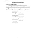
TROUBLE SHOOTING TABLE FOR PC I/F UNIT
(Continued)
Feed the composite video signal to
the INPUT4 terminal.
the INPUT4 terminal.
Using the control panel key or the
remote controller, select INPUT4.
remote controller, select INPUT4.
Select VIDEO as the signal type
on the user menu.
on the user menu.
Do the process
adjustment.
adjustment.
Is there the video signal at pin
(72) of IC8338?
(72) of IC8338?
Checking the video input
Does the image appear?
Is the image distorted?
Go to "Checking the
video sync signal".
video sync signal".
Go to "Checking the
video sync signal".
video sync signal".
Are the colors as specified?
The video input is okay. End.
Is the video signal as specified?
IC8338 defective.
5
NO
NO
NO
YES
YES
NO
YES
YES
5
6
XG-P25X
53
TROUBLE SHOOTING TABLE FOR PC I/F UNIT
(Continued)
6
NO
NO
NO
YES
YES
YES
7
Measure the VPC (IC8338)
clock signal at TL8004.
clock signal at TL8004.
Measure the signal at TL8140
on the oscilloscope screen.
(Check the vertical sync
signal.)
on the oscilloscope screen.
(Check the vertical sync
signal.)
Measure the signal at
TL8142 on the oscilloscope
screen. (Check the
horizontal sync signal.)
TL8142 on the oscilloscope
screen. (Check the
horizontal sync signal.)
Is the clock signal as
specified?
specified?
Go to "Checking the video
sync signal".
sync signal".
IC8338 defective.
IC8025 or its peripheral
parts defective.
parts defective.
Checking the video sync
signal
signal
Is the vertical sync
signal as specified?
signal as specified?
Is the horizontal sync
signal as specified?
signal as specified?
Go to "Checking the input
signal settings".
signal settings".
Input PWB defective.
XG-P25X
54
TROUBLE SHOOTING TABLE FOR PC I/F UNIT
(Continued)
7
NO
YES
YES
NO
Are there the horizontal and
vertical sync signals at
TL8130 and TL8131?
vertical sync signals at
TL8130 and TL8131?
IC8302 or its peripheral
parts defective.
parts defective.
IC8338 or its peripheral
parts defective.
parts defective.
Is there the specified clock
signal at FL8004?
signal at FL8004?
End.
XG-P25X
55
TROUBLE SHOOTING TABLE FOR PC I/F UNIT
(Continued)
Feed the DVI digital signal to the
INPUT3 terminal.
INPUT3 terminal.
Note: To ensure the Plug&Play system, first connect
the cable to the INPUT3 terminal and then turn on
the computer (signal generator) power.
the cable to the INPUT3 terminal and then turn on
the computer (signal generator) power.
Select INPUT3 for input terminal.
Checking the DVI digital input
Does the image appear?
Is the image free from distortion?
Are the colors as specified?
The DVI digital input is okay.
IC8298 or its peripheral
parts defective.
parts defective.
Measure the vertical sync signal at
the land of C8463 and the
horizontal sync signal at the land
of C8484. (The capacitors are
located on the back of the PWB.)
the land of C8463 and the
horizontal sync signal at the land
of C8484. (The capacitors are
located on the back of the PWB.)
Are the sync signals as specified?
Measure the clock signal at
R8685 (located on the back of
the PWB).
R8685 (located on the back of
the PWB).
Is the clock signal as specified?
IC8299 or its peripheral parts
defective.
defective.
Is the signal at the R4
terminal at low level?
terminal at low level?
IC8298 or its peripheral
parts defective.
parts defective.
NO
YES
YES
YES
YES
YES
YES
NO
NO
NO
NO
NO
Click on the first or last page to see other XG-P25XE (serv.man12) service manuals if exist.

