Sharp XG-P25XE (serv.man12) Service Manual ▷ View online
XG-P25X
48
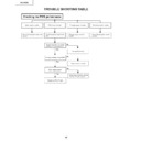
TROUBLE SHOOTING TABLE FOR PC I/F UNIT
(Continued)
Make the RGB signal settings.
Call the process mode.
Select R, G and B
individually from the pattern
menu.
individually from the pattern
menu.
Set the signal generator for
the gray-scale signal in order
to check the input signal.
the gray-scale signal in order
to check the input signal.
Measure the gray-scale
signals at TP8001, TP8002
and TP8003 on the
oscilloscope screen.
signals at TP8001, TP8002
and TP8003 on the
oscilloscope screen.
Checking the RGB signals
Is the signal type selected
for RGB?
for RGB?
Go to "Checking the GA4
and its peripheral parts".
and its peripheral parts".
Are the gray-scale signals at
TP8001, TP8002 and
TP8003 as specified?
TP8001, TP8002 and
TP8003 as specified?
Are there the input signals at
C8068 and C8061?
C8068 and C8061?
Input PWB defective.
IC8004 or its peripheral
parts defective.
parts defective.
IC8025 or its peripheral parts
defective.
defective.
NO
NO
NO
YES
YES
YES
XG-P25X
49
TROUBLE SHOOTING TABLE FOR PC I/F UNIT
(Continued)
Checking the GA4 and its
peripheral parts
peripheral parts
Measure the signals at
FB8004, FB8005 and
FB8006 on the oscilloscope
screen.
FB8004, FB8005 and
FB8006 on the oscilloscope
screen.
Select R, G and B individually
from the process mode
pattern menu.
from the process mode
pattern menu.
Measure the signals at
TL8106, TL8107, TL8108,
TL8109, TL8110 and TL8111
on the oscilloscope screen.
TL8106, TL8107, TL8108,
TL8109, TL8110 and TL8111
on the oscilloscope screen.
Are the R, G and B video
output signals as specified?
output signals as specified?
GA4 checking ended.
Are the signals selected on
the pattern menu and those
being measured just the
same?
the pattern menu and those
being measured just the
same?
Output PWB defective.
Are there clock signals at
pins (31), (32) and (33) of
IC8051?
pins (31), (32) and (33) of
IC8051?
Is there the 32.5-MHz
clock signal at
TP8114?
clock signal at
TP8114?
IC8029 defective.
Is there the 32.5-MHz
clock signal at
FB8110?
clock signal at
FB8110?
IC8025 defective.
X8005 defective.
Are the signals selected on
the pattern menu and those
being measured just the
same?
the pattern menu and those
being measured just the
same?
IC8029 defective.
IC8025 defective.
YES
YES
NO
NO
NO
YES
YES
YES
NO
NO
YES
NO
XG-P25X
50
TROUBLE SHOOTING TABLE FOR PC I/F UNIT
(Continued)
Feed the component signals to the
INPUT 1 or INPUT2 terminal.
INPUT 1 or INPUT2 terminal.
Using the control panel key or the
remote controller, select INPUT1
or INPUT2.
remote controller, select INPUT1
or INPUT2.
Do the process adjustment.
Set the signal type to the
component.
component.
Checking the component input
(4801 not included)
(4801 not included)
Does the image appear?
Go to "Checking the SOG circuit".
Are the colors as specified?
Is the signal type set for the
component?
component?
Is the image contour as specified?
IC8004 or IC8025 defective.
The component signals are as
specified. End.
specified. End.
4
NO
YES
YES
NO
YES
YES
NO
NO
4
XG-P25X
51
TROUBLE SHOOTING TABLE FOR PC I/F UNIT
(Continued)
Checking the SOG circuit
Measure the signal at
TL8136 on the oscilloscope
screen.
TL8136 on the oscilloscope
screen.
Measure the land of C8069
on the oscilloscope screen.
on the oscilloscope screen.
Are the composite sync
signals reproduced in the
specified timing?
signals reproduced in the
specified timing?
The SOG circuit is okay.
End.
End.
Is there the Y signal with the
sync signal added?
sync signal added?
Go to "Checking the input
signal settings".
signal settings".
Input PWB defective.
SOG sync pulse separation
circuit defective.
circuit defective.
In the process adjustment,
readjust the output line.
readjust the output line.
Checking the onscreen
display
display
Are the onscreen display
colors as specified?
colors as specified?
Go to "Checking the GA4
and its peripheral parts".
and its peripheral parts".
Reprogram the flash ROM.
0
YES
NO
NO
NO
YES
YES
Click on the first or last page to see other XG-P25XE (serv.man12) service manuals if exist.

