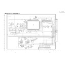
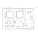
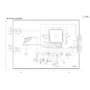
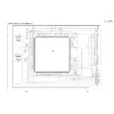
Sharp PG-C30XE (serv.man18) Service Manual / Technical Bulletin ▷ View online
LV047
Sharp Electronics (UK) Ltd., Technical Services Group
Date:
14 March 2001
Model: PGC30XE
Ref.:
Ref.:
001
Colour: White
Page:
Page:
1 of 15
1. Model Name:
PGC30XE
2. General:
Please be informed about a service procedure for the following phenomenon, that may
occur in a small number of units released in the market.
occur in a small number of units released in the market.
3. Description:
The flicker (looks like moving up and down) appears at the border around icon buttons or
menu bars etc. in Windows environment at RGB input.
menu bars etc. in Windows environment at RGB input.
4. Action:
If you have a service call from customer with above model as this phenomenon, please
modify the unit according to the attached instructions.
modify the unit according to the attached instructions.
New Parts
Ref. No.
Parts code
Price rank
Parts name
C1493
C1494
C1495
C1494
C1495
VCCCCY1HH220J
AA
Capacitor, 22pF 50V
X8005
9DK001-80023
AR
Crystal, 18.75MHz
-
9DK001-99046
AF
Lead wire, 15mm
<Interchange>
1. Interchangeable.
4. Not interchangeable.
2. Current type can be used in place of new type.
New type cannot be used in place of current type.
New type cannot be used in place of current type.
5. Interchangeable if replaced with same types of
related parts in used.
related parts in used.
3. Current type cannot be used in place of new type.
New type can be used in place of current type.
New type can be used in place of current type.
6. Others.
Parts marked with “ ” is important for maintaining the safety of the set. Be sure to replace these parts
with specified ones for maintaining the safety and performance of the set.
with specified ones for maintaining the safety and performance of the set.
FLICKER AT RGB INPUT
TECHNICAL BULLETIN
LV047
Sharp Electronics (UK) Ltd., Technical Services Group
Modification Instructions for PG-C30X RGB flicker
Contents
Pages
Modification of OUTPUT unit and PC I/F unit
2
Installation of new system program and GA4 data
6
Adjustment of PSIG-H, and Check of RGB/VIDEO
15
Modification of OUTPUT unit and PC I/F unit
Procedure
Refer to
Preparation
1. Remove the upper and rear cabinet.
2. Remove the four PC I/F unit lock screws, and take out the PC I/F unit.
2. Remove the four PC I/F unit lock screws, and take out the PC I/F unit.
It is unnecessary to remove the OUTPUT unit.
Modification of PC I/F unit
Pages 3-4 (Figure 1-2)
1. Add a 15mm lead wire (9DK001-99046) between TL616 and TL59.
2. Remove the 0 Ohm resistors FL46 and R235.
3. Change a crystal X8005 to 18.75MHz type (9DK001-80023).
2. Remove the 0 Ohm resistors FL46 and R235.
3. Change a crystal X8005 to 18.75MHz type (9DK001-80023).
Modification of OUTPUT UNIT
Page 5 (Figure 3)
1. Add the three 22pF capacitors (VCCCCY1HH220J) in parallel
on the resistors, R1404, R1405 and R1406.
LV047
Sharp Electronics (UK) Ltd., Technical Services Group
Modification of PC I/F unit
Figure 1
When installing the system software to the unit,
set the S1 switch to the WRITE mode.
set the S1 switch to the WRITE mode.
Add a 15mm lead wire (9DK001-99046) between TL616 and TL59.
Do not put the lead wire on the ICs.
Do not put the lead wire on the ICs.
LV047
Sharp Electronics (UK) Ltd., Technical Services Group
Modification of PC I/F unit
Figure 2
Remove the 0 Ohm resistors, FL46 and R235.
Change a crystal (X8005) to 18.75MHz type (
9DK001-80023).

