Sharp MX-RBX1 (serv.man12) Service Manual ▷ View online
MX-FNX2/AR-PN1/MX-RBX1 ELECTRICAL SECTION 10 – 5
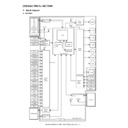
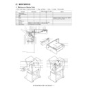
B. MX-RBX1
8
7
6
5
5
6
7
8
D
C
B
A
MX-RBX1
MX-FNX2/AR-PN1/MX-RBX1 ELECTRICAL SECTION 10 – 6
4
3
2
1
A
B
C
D
1
2
3
4
1/1
RELAY FEED UNIT COVER SENSOR
(FJPDD)
RELAY FEED MOTOR (FJPM)
RELAY FEED UNIT EXIT SENSOR
(FJPOD)
(FJPOD)
RELAY FEED UNIT ENTRANCE
(FJPID)
(FJPID)
ENTRANCE REVERSE PASS
SOLENOID (FINRPS)
SOLENOID (FINRPS)
REKAT FAN (FJFM)
MX-FNX2/AR-PN1/MX-RBX1 ELECTRICAL SECTION 10 – 7
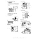
C. AR-PN1A/B/C/D
A
B
C
D
876
5
4
3
21
1
2
3
4
5
6
7
8
D
C
B
A
A
B
C
D
876
5
4
3
21
1
2
3
4
5
6
7
8
D
C
B
A
A
B
C
D
876
5
4
3
21
1
2
3
4
5
6
7
8
D
C
B
A
A
B
C
D
876
5
4
3
21
1
2
3
4
5
6
7
8
D
C
B
A
1/1
AR-PN1A/B/C/D
1
2
1
2
J2006
J2006
W
aste
full
photosensor
circuit
PCB
1
2
1
2
J2005
J2005
W
aste
full
LED
circuit
PCB
5
4
3
2
1
J1001
J1001
5
4
3
2
1
J2004
5
4
3
2
1
5
4
3
2
1
J1004
1
2
3
4
5
6
7
8
9
10
1
2
3
4
5
6
7
8
9
10
10
9
8
7
6
5
4
3
2
1
J1002
J1002
1
2
1
2
9
8
7
6
5
4
3
2
1
J1006
J1006
J1007
J2011-1
J2011-2
J2011-3
J2011-4
J2011-5
J2011-6
J2011-7
J2010-1
J2010-2
J2010-3
J2010-4
J2010-5
J2010-6
1
2
J2002
J2001
1
2
3
4
5
6
7
1
2
3
4
5
6
7
J201
1
J201
1
J1007-13
J1007-12
J1007-1
1
J1007-10
J1007-9
J1007-8
J1007-7
1
2
3
4
5
6
1
2
3
4
5
6
J2010
J2010
J1007-6
J1007-5
J1007-4
J1007-3
J1007-2
J1007-1
FPSM
FPSHPD
1
2
3
1
2
3
J2009
FPMCK
FPHPD
M
CN14
M
FPNM
13
12
11
10
9
8
7
6
5
4
3
2
1
13
12
11
10
9
8
7
6
5
4
3
2
1
J1007
4
3
2
1
J1005
J1005
4
3
2
1
9
8
7
6
5
4
3
2
1
1
2
3
1
2
3
J2008
1
2
3
1
2
3
J2007
1
2
3
4
Punch
motor
Punch
horizontal
registration
home
position
sensor
Punch
home
position
sensor
Punch
horizontal
registration
motor
Photosensor
circuit
PCB
LED
circuit
PCB
Punch
controller
PCB
Finisher
section
Punch
motor
lock
sensor
J2003
J1003
10
9
8
7
6
5
4
3
2
1
5
4
3
2
1
5
4
3
2
1
CN14
CN12
CN12
MX-FNX2/AR-PN1/MX-RBX1 ELECTRICAL SECTION 10 – 8
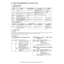
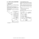
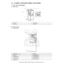
3. LEDs and Check Pins by PCB
Of the LEDs and check pins used in the machine, those needed
during servicing in the field are discussed.
during servicing in the field are discussed.
NOTE: Do not touch the check pins not found in the list herein.
They are exclusively for factory use, and require special
tools and a high degree of accuracy
tools and a high degree of accuracy
A. Finisher Controller PCB
B. Punch Controller PCB
Switch
Description
SW1
Folding position adjustment, middle 2-point stapling
adjustment etc.
adjustment etc.
PSW1
Folding position adjustment, middle 2-point stapling
adjustment etc.
adjustment etc.
PSW2
Folding position adjustment, middle 2-point stapling
adjustment etc.
adjustment etc.
Switch
Description
SW1001
Punch hole count registration/sensor output adjustment etc.
SW1002
Punch hole count registration/sensor output adjustment etc.
SW1003
Punch hole count registration/sensor output adjustment etc.
SW1
LED1
PSW2
LED2
CB1
PSW1
1
CN9
9
CN11
1
7
CN16
CN12
CN1
CN14
CN23
5
1
CN21
1
4
CN22
1
3
1
17
18
34
81
1
5
CN19
CN20
3
14
1
CN2
1
12
CN8
CN6
CN10
CN3
CN13
CN5
CN4
CN7
CN15
6
1
4
1
1
12 1
10
CN17
6
1
1
6
CN18
2
1
1
7
9
5
1
1
15
1
12
1
SW1001
LED1001
LED1002
LED1003
LED1002
LED1003
2
1
1
59
1
J1003
J1004
J1002
J1001
J1006
J1005
J1007
14
SW1002
SW1003
1
5
1
10
13
1
Display

