Sharp MX-RBX1 (serv.man11) Service Manual ▷ View online
MX-FNX2/AR-PN1/MX-RBX1 SELF DIAG MESSAGE AND TROUBLE CODE 9 – 5
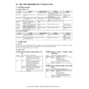
f. F1-11, Stack Delivery Motor (FAM) Fault
g. F1-15, Lift Motor (FLM) Fault
h. F1-15, Lift Motor (FLM) Fault
i. F1-15, Shift Motor (FLM) Fault
j. F1-19, Alignment Motor (front) Fault
k. F1-20, Alignment Motor (Rear; FRJM) Fault
Cause/Trouble section
Procedure
Check
Result
Remedy
Delivery belt home position sensor
(FOBHPD)
(FOBHPD)
1
Check the delivery belt home position sensor (FOBHPD).
Is the sensor normal?
Is the sensor normal?
NO
Replace the sensor.
Wiring
2
Is the wiring between the finisher controller PCB and the
stack delivery motor (FAM) normal?
stack delivery motor (FAM) normal?
NO
Correct the wiring.
Stack delivery roller
3
Try turning the stack delivery motor (FAM) by hand.
Is the rotation smooth?
Is the rotation smooth?
NO
Correct the mechanical
system.
system.
Stack delivery motor (FAM), Finisher
controller PCB
controller PCB
4
Try replacing the stack delivery motor (FAM).
Is the problem corrected?
Is the problem corrected?
YES
End.
NO
Replace the finisher
controller PCB.
controller PCB.
Cause/Trouble section
Procedure
Check
Result
Remedy
Paper surface sensor (FSLD)
1
Check the paper surface sensor (FSLD).
Is the sensor normal?
Is the sensor normal?
NO
Replace the sensor.
Tray up/down mechanism
2
Check the tray up/down mechanism. Is the mechanism
normal?
normal?
NO
Correct the mechanism.
Finisher controller PCB
3
Is 24 VDC supplied from the finisher controller PCB to the lift
motor (FLM) as soon as the tray is driven?
motor (FLM) as soon as the tray is driven?
NO
Replace the finisher
controller PCB.
controller PCB.
Lift motor (FLM), Wiring
4
Check the wiring from the finisher controller PCB to the lift
motor (FLM); is it normal?
motor (FLM); is it normal?
YES
Replace the lift motor (FLM).
NO
Correct the wiring.
Cause/Trouble section
Procedure
Check
Result
Remedy
Tray position
1
Is the tray as far as the lift upper limit sensor (FULD)?
YES
Lower the position of the
tray.
tray.
Lift upper limit sensor (FULD)
2
Check the lift upper limit sensor (FULD). Is the sensor
normal?
normal?
NO
Replace the sensor.
Finisher controller PCB, Wiring
3
Check the wiring from the finisher controller PCB to the lift
upper limit sensor (FULD); is it normal?
upper limit sensor (FULD); is it normal?
YES
Replace the finisher
controller PCB.
controller PCB.
NO
Correct the wiring.
Cause/Trouble section
Procedure
Check
Result
Remedy
-
1
Is the tray in UP position?
YES
Go to step 4).
NO
Go to step 2).
Finisher controller PCB
2
Is power supplied to the finisher controller PCB as soon as
the tray is driven?
the tray is driven?
YES
Go to step 3).
NO
Replace the finisher
controller PCB.
controller PCB.
Tray up/down mechanism, lift motor
(FLM)
(FLM)
3
Is there a fault in the tray up/down mechanism?
YES
Correct the tray up/down
mechanism.
mechanism.
NO
Replace the tray up/down
motor.
motor.
Lift motor lock (FLE), Finisher controller
PCB
PCB
4
Check the lift motor lock sensor (FLE).
Is the sensor normal?
Is the sensor normal?
YES
Replace the finisher
controller PCB.
controller PCB.
NO
Replace the sensor.
Cause/Trouble section
Procedure
Check
Result
Remedy
Alignment plate home position sensor
(front; FFJHPD)
(front; FFJHPD)
1
Check the alignment home position sensor (front; FFJHPD).
Is the sensor normal?
Is the sensor normal?
NO
Replace the sensor.
Wiring
2
Is the wiring between the finisher controller PCB and the
alignment plate motor (front; FFJM) normal?
alignment plate motor (front; FFJM) normal?
NO
Correct the wiring.
Alignment plate (front)
3
Is there mechanical trapping in the alignment plate path?
YES
Correct the mechanical
system.
system.
Alignment motor (front; FFJM), Finisher
controller PCB
controller PCB
4
Try replacing the alignment motor (front; FFJM).
Is the problem corrected?
Is the problem corrected?
YES
End.
NO
Replace the finisher
controller PCB.
controller PCB.
Cause/Trouble section
Procedure
Check
Result
Remedy
Alignment home position sensor (rear;
FRJHPD)
FRJHPD)
1
Check the alignment home position sensor (rear; FRJHPD).
Is the sensor normal?
Is the sensor normal?
NO
Replace the sensor.
Wiring
2
Is the wiring between the finisher controller PCB and the
alignment motor (rear; FRJM) normal?
alignment motor (rear; FRJM) normal?
NO
Correct the wiring.
Alignment plate (rear)
3
Is there mechanical trapping in the path of the alignment
plate?
plate?
YES
Correct the mechanical
mechanism.
mechanism.
Alignment motor (rear; FRJM), Finisher
controller PCB
controller PCB
4
Try replacing the alignment motor (rear; FRJM).
Is the problem corrected?
Is the problem corrected?
YES
End.
NO
Replace the finisher controller
PCB.
PCB.
MX-FNX2/AR-PN1/MX-RBX1 SELF DIAG MESSAGE AND TROUBLE CODE 9 – 6
l. F1-30, Communication error
m. F1-37, Finisher Unit Back-Up RAM Fault
n. F1-80, Finisher Unit Power Supply Fault
o. F1-81, Feed Motor (FFM) Fault
(2) Punch Unit, option
a. F1-32, Communication Faulty
b. F1-33, Punch Horizontal Registration Motor (FPSM) Fault
Cause/Trouble section
Procedure
Check
Result
Remedy
Finisher controller PCB, Host machine
DC controller PCB
DC controller PCB
1
Turn off and then on the host machine. Is the problem
corrected?
corrected?
YES
End.
Wiring
2
Is the wiring between the finisher controller PCB and the DC
controller PCB of the host machine normal?
controller PCB of the host machine normal?
NO
Correct the wring.
Finisher controller PCB, Host machine
DC controller PCB
DC controller PCB
3
Try replacing the finisher controller PCB and the host
machine DC controller PCB. Is the problem corrected?
machine DC controller PCB. Is the problem corrected?
YES
End.
Cause/Trouble section
Procedure
Check
Result
Remedy
Finisher controller PCB
1
Turn off and then on the host machine. Is the problem
corrected?
corrected?
YES
End.
NO
Replace the finisher controller
PCB.
PCB.
Cause/Trouble section
Procedure
Check
Result
Remedy
Finisher controller PCB, Host machine
DC controller PCB
DC controller PCB
1
Turn off and then on the host machine. Is the problem
corrected?
corrected?
YES
End.
Wiring
2
Is the wiring between the finisher controller PCB and the
host machine DC controller PCB normal?
host machine DC controller PCB normal?
NO
Correct the wiring.
Power supply
3
Measure the voltage between CN1-1 (+) and CN1-3 (-)/CN2-
1 (+) and CN2-3 (-) on the finisher controller PCB. Is it 24
VDC?
1 (+) and CN2-3 (-) on the finisher controller PCB. Is it 24
VDC?
YES
Replace the finisher controller
PCB.
PCB.
NO
Replace the host machine
DC controller PCB.
DC controller PCB.
Cause/Trouble section
Procedure
Check
Result
Remedy
Bookbinding roller home position
sensor (FFRHPD)
sensor (FFRHPD)
1
Check the bookbinding roller home position sensor
(FFRHPD).
Is it normal?
(FFRHPD).
Is it normal?
NO
Replace the sensor.
Wiring
2
Is the wiring between the finisher controller PCB and the
feed motor (FFM) normal?
feed motor (FFM) normal?
NO
Correct the wiring.
Feed roller
3
Try turning the stack feed roller (upper) shaft by hand.
Does the stack feed roller (upper) move up/down normally?
Does the stack feed roller (upper) move up/down normally?
NO
Correct the mechanical
system.
system.
Feed motor (FFM), Finisher controller
PCB
PCB
4
Try replacing the feed motor (FFM). Is the problem
corrected?
corrected?
YES
End.
NO
Replace the finisher controller
PCB.
PCB.
Cause/Trouble section
Procedure
Check
Result
Remedy
Finisher controller PCB, Punch
controller PCB
controller PCB
1
Turn off and the on the host machine. Is the problem
corrected?
corrected?
YES
End.
Wiring
2
Is the wiring between the finisher controller PCB and the
punch controller PCB normal?
punch controller PCB normal?
NO
Correct the wiring.
Power supply
3
Measure the voltage between CN14-5 (+) and CN14-3 (-) on
the finisher controller PCB. Is it 24 VDC?
the finisher controller PCB. Is it 24 VDC?
NO
Replace the finisher controller
PCB.
PCB.
YES
Replace the punch controller
PCB.
PCB.
Cause/Trouble section
Procedure
Check
Result
Remedy
Punch horizontal registration home
position sensor (FPSHPD)
position sensor (FPSHPD)
1
Check the punch horizontal registration home position
sensor (FPSHPD).
Is the sensor normal?
sensor (FPSHPD).
Is the sensor normal?
NO
Replace the sensor.
Wiring
2
Is the wiring between the finisher controller PCB and the
punch horizontal registration home position sensor
(FPSHPD) normal?
punch horizontal registration home position sensor
(FPSHPD) normal?
NO
Correct the wiring.
Horizontal registration mechanism,
punch horizontal registration motor
(FPSM)
punch horizontal registration motor
(FPSM)
3
Is there a fault in the horizontal registration mechanism?
YES
Correct the horizontal
registration mechanism.
registration mechanism.
NO
Replace the punch horizontal
registration motor (FPNM).
registration motor (FPNM).
Punch controller PCB, Finisher
controller PCB
controller PCB
4
Try replacing the punch controller PCB. Is the problem
corrected?
corrected?
YES
End.
NO
Replace the finisher
controller PCB.
controller PCB.
MX-FNX2/AR-PN1/MX-RBX1 SELF DIAG MESSAGE AND TROUBLE CODE 9 – 7
c. F1-34, Punch Motor (FPNM) Fault
d. F1-35, Punch Horizontal Registration Home Position Sensor (FPSHPD) Fault
e. F1-38, Punch Unit Back-UP RAM Fault
f. F1-39, Waste Full Sensor Fault
g. F1-40, Punch Unit Power Supply Fault
Cause/Trouble section
Procedure
Check
Result
Remedy
Punch home position sensor (FPHPD)
1
Check the punch home position sensor (FPHPD).
Is the sensor normal?
Is the sensor normal?
NO
Replace the sensor.
Punch motor lock sensor (FPMCK)
2
Check the punch motor lock sensor (FPMCK). Is the sensor
normal?
normal?
NO
Replace the sensor.
Wiring
3
Is the wiring between the finisher controller PCB and the
sensor normal?
sensor normal?
NO
Correct the wiring.
Punch mechanism, Punch motor
(FPNM)
(FPNM)
4
Is there a fault in the punch mechanism?
YES
Correct the punch
mechanism.
mechanism.
NO
Replace the punch motor
(FPNM).
(FPNM).
Punch controller PCB, Finisher
controller PCB
controller PCB
5
Try replacing the punch controller PCB. Is the problem
corrected?
corrected?
YES
End.
NO
Replace the fisher controller
PCB.
PCB.
Cause/Trouble section
Procedure
Check
Result
Remedy
Horizontal registration sensor
(photosensor PCB/LED PCB)
(photosensor PCB/LED PCB)
1
Check the horizontal registration sensor. Is the sensor
normal?
normal?
NO
Replace the sensor.
Wiring
2
Check the punch motor lock sensor (FPMCK).
Is the sensor normal?
Is the sensor normal?
NO
Correct the wiring.
Punch controller PCB, Finisher
controller PCB
controller PCB
3
Try replacing the punch controller PCB. Is the problem
correct?
correct?
YES
End.
NO
Replace the finisher
controller PCB.
controller PCB.
Cause/Trouble section
Procedure
Check
Result
Remedy
Punch controller PCB
1
Turn off and the on the host machine. Is the problem
corrected?
corrected?
YES
End.
NO
Replace the punch controller
PCB.
PCB.
Cause/Trouble section
Procedure
Check
Result
Remedy
Waste full Sensor (waste full
photosensor PCB/waste full LED PCB)
photosensor PCB/waste full LED PCB)
1
Check the waste full sensor. Is the sensor normal?
NO
Replace the sensor.
Wiring
2
Is the wiring between the punch controller PCB and the
waste full sensor normal?
waste full sensor normal?
NO
Correct the wiring.
Punch controller PCB, Finisher
controller PCB
controller PCB
3
Try replacing the punch controller PCB. Is the problem
corrected?
corrected?
YES
End.
NO
Replace the finisher controller
PCB.
PCB.
Cause/Trouble section
Procedure
Check
Result
Remedy
Finisher controller PCB, Host machine
DC controller PCB
DC controller PCB
1
Turn off and then off the host machine. Is the problem
corrected?
corrected?
YES
End.
Wiring
2
Is the wiring between the finisher controller PCB and the
punch controller PCB normal?
punch controller PCB normal?
NO
Correct the wiring.
Power supply
3
Measure the voltage between CN14-5 (+) and CN4-3 (-) on
the finisher controller PCB. Is it 24 VDC?
the finisher controller PCB. Is it 24 VDC?
YES
Replace the punch controller
PCB.
PCB.
NO
Replace the finisher controller
PCB.
PCB.
MX-FNX2/AR-PN1/MX-RBX1 SELF DIAG MESSAGE AND TROUBLE CODE 9 – 8
(3) Paper pass (Paper transport section)
a. The transport motor (FFM) does not operate.
b. A fan motor alarm is generated.
c. A paper jam occurs in the entry port of the interface
transport unit.
transport unit.
Case 1
Cause
Connector pin loose connection
Check &
Remedy
Remedy
Check connection of the connectors.
(CN309, CN307, CN306, CN303, CN301, CN21)
(CN309, CN307, CN306, CN303, CN301, CN21)
Case 2
Cause
Harness disconnection
Check &
Remedy
Remedy
Execute the conduction test between connectors. If
disconnection is found, replace the defective
connectors.
disconnection is found, replace the defective
connectors.
Case 3
Cause
Motor lead breaking
Check &
Remedy
Remedy
Execute the conduction test of coil. If disconnection
is found, replace the coil.
is found, replace the coil.
Case 4
Cause
Control PWB trouble
Check &
Remedy
Remedy
If the motor does not operate in the motor
individual operation mode, replace the control
PWB.
individual operation mode, replace the control
PWB.
Case 1
Cause
Pinching
Check &
Remedy
Remedy
Visually check the suction port and remove foreign
materials.
materials.
Case 2
Cause
Connector pin loose connection
Check &
Remedy
Remedy
Check connection of the connectors.
(CN313, CN307, CN306, CN304, CN301, CN22,
CN23)
(CN313, CN307, CN306, CN304, CN301, CN22,
CN23)
Case 3
Cause
Harness disconnection
Check &
Remedy
Remedy
Execute the conduction test between connectors. If
disconnection is found, replace the defective
connectors.
disconnection is found, replace the defective
connectors.
Case 4
Cause
Motor trouble
Check &
Remedy
Remedy
If the motor does not operate in the motor
individual operation mode, replace the motor.
individual operation mode, replace the motor.
Case 5
Cause
Control PWB trouble
Check &
Remedy
Remedy
If the motor does not operate in the motor
individual operation mode, replace the control
PWB.
individual operation mode, replace the control
PWB.
Case 1
Cause
Flapper solenoid connector pin loose connection
Check &
Remedy
Remedy
Check connection of the connectors.
(CN312, CN307, CN306, CN304, CN301, CN22,
CN23)
(CN312, CN307, CN306, CN304, CN301, CN22,
CN23)
Case 2
Cause
Harness disconnection
Check &
Remedy
Remedy
Execute the conduction test between connectors. If
disconnection is found, replace the defective
connectors.
disconnection is found, replace the defective
connectors.
Case 3
Cause
Flapper solenoid trouble
Check &
Remedy
Remedy
If there is no conduction between CN312 1 pin and
2pin, replace the solenoid.
2pin, replace the solenoid.
Case 4
Cause
Control PWB trouble
Check &
Remedy
Remedy
If the flapper does not operate in the individual
operation mode, replace the control PWB.
operation mode, replace the control PWB.
Case 1
Cause
Paper jam
Check &
Remedy
Remedy
Visually check to remove paper jam.
Cause
Sensor connector pin loose connection
Check &
Remedy
Remedy
Check connection of the connectors.
(CN310, CN311, CN307, CN306, CN304, CN301,
CN22, CN23)
(CN310, CN311, CN307, CN306, CN304, CN301,
CN22, CN23)
Case 2
Cause
Harness disconnection
Check &
Remedy
Remedy
Execute the conduction test between connectors. If
disconnection is found, replace the defective
connectors.
disconnection is found, replace the defective
connectors.
Cause
Sensor trouble
Check &
Remedy
Remedy
Replace the sensor at the paper jam position.
Case 3
Cause
Sensor flag operation trouble
Check &
Remedy
Remedy
Visually check the sensor flag operation. If it is
caught in the operation, replace the sensor flag.
caught in the operation, replace the sensor flag.
Case 4
Cause
Control PWB trouble
Check &
Remedy
Remedy
If the sensor level varies but the phenomenon
remains when each sensor is turned ON/OFF,
replace the control PWB.
remains when each sensor is turned ON/OFF,
replace the control PWB.
Display

