Sharp MX-RBX1 (serv.man10) Service Manual ▷ View online
MX-FNX2/AR-PN1/MX-RBX1 ADJUSTMENTS 8 – 2
C. Registering the Number of Punch Hole
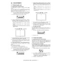
Perform the following to register the type of punch unit (number of
holes) used to the IC on the punch controller PCB for identification
by the finisher. Be sure to register the type whenever you have
replaced the punch controller PCB.
1)
holes) used to the IC on the punch controller PCB for identification
by the finisher. Be sure to register the type whenever you have
replaced the punch controller PCB.
1)
Set bits 1 through 4 on the DIPSW1001 on the punch control-
ler PCB as follows:
ler PCB as follows:
2)
Press SW1002 on the punch controller PCB to select the
appropriate number of punch holes.
• Each press on SW1002 moves the selection through the fol-
appropriate number of punch holes.
• Each press on SW1002 moves the selection through the fol-
lowing (repeatedly from top to bottom).
3)
Press SW1003 on the punch controller PCB twice. The
presses will store the selected number of punch holes on the
punch controller PCB.
• A single press on SW1003 will cause the LED indication to
presses will store the selected number of punch holes on the
punch controller PCB.
• A single press on SW1003 will cause the LED indication to
flash; another press on SW1003 will cause the indication to
remain ON to indicate the end of registration.
remain ON to indicate the end of registration.
4)
Shift all bits of DIPSW1001 to OFF.
D. After Replacing the EEP-ROM (IC1002)
1)
Turn off the host machine.
2)
Set bits 1 through 4 on the punch controller PCB as follows:
3)
Press SW1002 and SW1003 on the punch controller PCB at
the same time.
• The presses will initialize the EEP-ROM. At the end, all
the same time.
• The presses will initialize the EEP-ROM. At the end, all
LEDs (LED1001, LED1002, LED1003) will go ON.
4)
Adjust the sensor output, and store the number of punch
holes. Adjust the punch hole position adjustment (horizontal
registration) of necessary.
holes. Adjust the punch hole position adjustment (horizontal
registration) of necessary.
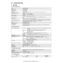
E. Setup by the diag simulation of the host
machine
1)
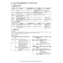
Select "FINISHER ADJUSTMENT" in SIM 3-10.
2)
Select a setup item and change the setup value.
Adjustable setup range is as follows.
Number of punch holes
LED1001
LED1002
LED1003
2 holes (Punch Unit-J1)
ON
OFF
OFF
2/3 holes (Punch Unit-K1)
ON
ON
OFF
4 holes (Punch Unit-G1)
OFF
ON
OFF
4 holes (Punch Unit-H1)
OFF
OFF
ON
ON
1
2
3
4
ON
1
2
3
4
Adjustment content
Default
value
Setup
range
range
Change/Setup
value 1
1
Saddle binding position
adjustment
adjustment
200
0 - 400
0.0707mm
2
Saddle folding position
adjustment
adjustment
200
0 - 400
0.0525mm
3
Front alignment position
adjustment
adjustment
10
0 - 20
0.367mm
4
Rear alignment position
adjustment
adjustment
10
0 - 20
0.367mm
5
Staple front one-position
binding position adjustment
binding position adjustment
100
0 - 200
0.04374mm
6
Staple rear one-position
binding position adjustment
binding position adjustment
100
0 - 200
0.04374mm
7
Staple 2-position binding
center adjustment
center adjustment
100
0 - 200
0.04374mm
8
Staple 2-position binding
pitch adjustment
pitch adjustment
50
0 - 100
0.04374mm
9
Punch center position
adjustment (FR direction)
adjustment (FR direction)
50
47 - 53
10
Punch hole position
adjustment (paper feed
direction)
adjustment (paper feed
direction)
50
0 - 100
0.105mm
OK
10-key
0
A:
A:200
B:200
C: 10
D:100
; SADDLE POSITION
; FOLDING POSITION
; FRONT ADJUSUT
; REAR ADJUSUT
SIMULATION NO.03-10
FINISHER ADJUSTMENT
200
[197-203]
OK
TEST
CLOSE
0
A:
A:197
B:200
C: 10
D:100
; SADDLE POSITION
; FOLDING POSITION
; FRONT ADJUSUT
; REAR ADJUSUT
SIMULATION NO.03-10
FINISHER ADJUSTMENT
197
[197-203]
OK
TEST
CLOSE
Display

