Sharp MX-5500N / MX-6200N / MX-7000N (serv.man19) Peripheral ▷ View online
MX-FNX4 DISASSEMBLY AND ASSEMBLY 6 – 55
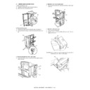
7) Disconnect the connector [16], and remove the harness from
the clamp and the edge saddle [17].
8) Remove the two screws [18], and pull out the stapling tray [19]
in the delivery direction.
CAUTION: When removing parts in the stapling tray, do not apply a
force to the alignment plates (front/back) and the three
positions on the rear edge regulation plate.
positions on the rear edge regulation plate.
l. Removal of swing unit discharge needle
1) Remove the screw [1] which is fixing the discharge needle at
1) Remove the screw [1] which is fixing the discharge needle at
the center of the swing unit.
2) Remove the two screws [2] which are fixing the earth wire of
the delivery side discharge needle.
3) Pull out the discharge needle [3] at the center of the swing unit
from the bottom.
4) Disengage the pawls [4] (at four positions) which are fixing the
discharge needle on the delivery side. Remove the two dis-
charge needles [5].
charge needles [5].
(3) Discharge needle 2
a. Removal of inlet port discharge needle
1)
1)
Open the upper door, and release the hook that links the upper
door and the inlet upper guide.
door and the inlet upper guide.
2)
Remove the two screws [1], and remove the right side section
[2] of the inlet upper guide.
[2] of the inlet upper guide.
3)
Remove the three screws [3], and remove the inlet discharge
needle [4].
needle [4].
(4) Saddle stitcher controller PCB (MX-FNX4)
a. PCB cover
1)
1)
Remove the seven screws [1], and remove the PCB cover [2].
[18]
[17]
[19]
[18]
[16]
[1]
[2]
[4]
[3]
[5]
[4]
[2]
[1]
[3]
[4]
[1]
[1]
[2]
MX-FNX4 DISASSEMBLY AND ASSEMBLY 6 – 56
b. Removal of saddle stitcher controller PCB
1) Remove the four screws [1] and sixteen connectors [2].
1) Remove the four screws [1] and sixteen connectors [2].
Remove the saddle stitcher controller PCB [3].
2. Paper pass unit (MX-RBX2)
A. Paper pass unit
1) Open the cover A of the main unit, and draw out the paper
pass unit.
2) Remove the paper pass unit.
(1) Paper pass unit inlet sensor
1)
Remove the paper pass unit.
2)
Loosen the screws, and remove the rear cabinet.
3)
Remove the paper pass unit inlet sensor.
(2) Paper pass unit outlet sensor
1)
Remove the paper pass unit.
2)
Remove the rear cabinet.
3)
Remove the paper pass unit outlet sensor.
[1]
[1]
[1]
[1]
[2]
[3]
1
A
1
2
1
1
2
3
1
1
2
3
MX-FNX4 DISASSEMBLY AND ASSEMBLY 6 – 57
(3) Upper guide flapper
1) Remove the paper pass unit.
2) Remove the rear cabinet.
3) Remove the stopper band A and bracket B, and remove the
2) Remove the rear cabinet.
3) Remove the stopper band A and bracket B, and remove the
upper guide unit.
* When installing the upper guide flapper, mount the bracket
so that it is aligned with the adjustment reference. If the
upper guide unit magnet is not fit snugly, adjust the bracket
until it is positioned properly.
upper guide unit magnet is not fit snugly, adjust the bracket
until it is positioned properly.
4) Remove the parts, and remove the upper guide flapper.
* When removing the resin lever, pay close attention not to
damage it.
(4) Paper pass fan
1)
Remove the paper pass unit.
2)
Remove the rear cabinet.
3)
Remove the bottom cover.
* When removing the bottom cover, pay attention for the
* When removing the bottom cover, pay attention for the
pawls located on the delivery side.
4)
Remove the clamp parts and the connector, and remove the
paper pass fan.
* When installing the paper pass fan, orient the label (A) to the
paper pass fan.
* When installing the paper pass fan, orient the label (A) to the
direction shown on the picture below.
(5) Paper pass motor
1)
Remove the paper pass unit.
2)
Remove the rear cabinet.
3)
Remove the bottom cover.
4)
Disconnect the connector, and remove the relay feed motor.
2
B
3
1
A
Adjustment reference
1
1
2
3
A
1
2
3
MX-FNX4 DISASSEMBLY AND ASSEMBLY 6 – 58
(6) Paper pass reverse pass solenoid
1) Remove the paper pass unit.
2) Remove the rear cabinet.
3) Remove the bottom cover.
4) Remove the front cover.
2) Remove the rear cabinet.
3) Remove the bottom cover.
4) Remove the front cover.
5) Remove the solenoid unit A.
6) Remove the parts, and remove the paper pass reverse pass
solenoid.
* Install the solenoid unit to the original position or the left
side.
(7) Inlet roller
1)
Remove the paper pass unit.
2)
Remove the rear cabinet.
3)
Remove the bottom cover.
4)
Remove the front cover.
5)
Remove the paper pass reverse pass solenoid, paper pass
fan, and the paper pass feed motor.
fan, and the paper pass feed motor.
6)
Remove the parts, and remove the inlet roller.
(8) Feed roller
1)
Remove the paper pass unit.
2)
Remove the rear cabinet.
3)
Remove the bottom cover.
4)
Remove the front cover.
5)
Remove the parts, and remove the feed roller.
3
A
2
1
21.5mm
1
1
2
1
1
2
Click on the first or last page to see other MX-5500N / MX-6200N / MX-7000N (serv.man19) service manuals if exist.

