Sharp MX-5500N / MX-6200N / MX-7000N (serv.man19) Peripheral ▷ View online
MX-FNX4 DISASSEMBLY AND ASSEMBLY 6 – 60
C. Left cabinet unit
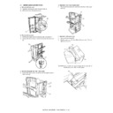
(1) Paper pass unit cover sensor
1) Remove the paper pass unit.
2) Remove the reverse tray.
3) Release the lock, and separate the saddle stitch finisher from
2) Remove the reverse tray.
3) Release the lock, and separate the saddle stitch finisher from
the main unit.
4) Remove the left cover.
5) Disconnect the connector, and remove the sensor bracket A.
Then, remove the paper pass unit cover sensor.
(2) Paper pass PCB
1) Remove the paper pass unit.
2) Remove the reverse tray.
3) Separate the saddle stitch finisher from the main unit.
4) Remove the left cover.
5) Remove the sensor bracket.
6) Remove the metal plates A on the left cover.
2) Remove the reverse tray.
3) Separate the saddle stitch finisher from the main unit.
4) Remove the left cover.
5) Remove the sensor bracket.
6) Remove the metal plates A on the left cover.
7)
Remove the hexagon screws, and take out the paper pass
PCB. Then, disconnect the connector.
PCB. Then, disconnect the connector.
3. Punch module (MX-PNX2A/B/C/D)
A. Outer cover
(1) Rear cover
a. Removing the rear cover
1)
1)
Remove the three screws [1] to remove the rear cover [2].
(2) Upper cover
a. Removing the rear cover
1)
1)
Remove the three screws [1] to remove the rear cover [2].
1
2
3
A
A
2
1
3
4
[1]
[2]
[1]
[2]
MX-FNX4 DISASSEMBLY AND ASSEMBLY 6 – 61
b. Removing the upper cover
1) Open the front door [1], and remove the three screws [2]. Pull
1) Open the front door [1], and remove the three screws [2]. Pull
out the dial [3], and remove the upper cover [4].
(3) Right guide
a. Removing the right guide
1) Remove the four screws [1] to remove the right guide [2].
1) Remove the four screws [1] to remove the right guide [2].
B. Drive system
(1) Punch motor
a. Removing rear cover
1) Remove the three screws [1] to remove the rear cover [2].
1) Remove the three screws [1] to remove the rear cover [2].
b. Removing the upper cover
1)
1)
Open the front door [1], and remove the three screws [2]. Pull
out the dial [3], and remove the upper cover [4].
out the dial [3], and remove the upper cover [4].
c. Removing punch motor
1)
1)
Disconnect the connector [1].
2)
Remove the two screws [2] to remove the punch motor [3].
(2) Horizontal registration motor
a. Removing rear cover
1)
1)
Remove the three screws [1] to remove the rear cover [2].
[2]
[1]
[4]
[3]
[4]
[2]
[1]
[2]
[1]
[2]
[2]
[1]
[4]
[3]
[4]
[2]
[2]
[3]
[1]
[1]
[2]
MX-FNX4 DISASSEMBLY AND ASSEMBLY 6 – 62
b. Removing right guide
1) Remove the four screws [1] to remove the right guide [2].
1) Remove the four screws [1] to remove the right guide [2].
c. Removing horizontal registration motor
1) Disconnect the connector [1].
2) Remove the two screws [2], and slide the horizontal registra-
1) Disconnect the connector [1].
2) Remove the two screws [2], and slide the horizontal registra-
tion motor [3] in the arrow direction to remove it.
(3) Punch module
a. Caution for removing punch module
CAUTION: The punch module may be opened during removal.
Open the punch module in advance, if necessary.
b. Removing rear cover
1) Remove the three screws [1] to remove the rear cover [2].
1) Remove the three screws [1] to remove the rear cover [2].
c. Removing right guide
1)
1)
Remove the four screws [1] to remove the right guide [2].
d. Removing the upper cover
1)
1)
Open the front door [1], and remove the three screws [2]. Pull
out the dial [3], and remove the upper cover [4].
out the dial [3], and remove the upper cover [4].
e. Removing punch module
1)
1)
Remove the E-ring [1], washer [2], and the punch spring [3].
[1]
[2]
[1]
[2]
[2] [3]
[1]
[2]
[1]
[2]
[2]
[1]
[4]
[3]
[4]
[2]
[3]
[1]
[2]
MX-FNX4 DISASSEMBLY AND ASSEMBLY 6 – 63
2) Turn the gear [1] in the arrow direction, and move the punch
module [2] to the front.
3) Remove the three screws [1] and the sensor base (upper) [2].
Then, disconnect the connector of the photo sensor PCB [3].
4) Disconnect the connector [1], and remove the screw [2]. Then,
remove the horizontal registration home position sensor [3].
5)
Turn the gear [1] into the arrow direction, and move the punch
module [2] to the back side.
module [2] to the back side.
6)
Hold the pawl of the tie wrap with lock [1], and remove it.
(Remove without cutting the tie wrap.)
(Remove without cutting the tie wrap.)
7)
Disconnect the three connectors [2], and remove the screw [3].
Then, remove the harness guide [4].
Then, remove the harness guide [4].
8)
First, lift the front side of the punch module [1], and move it in
the arrow direction. Then, remove the punch module [1].
the arrow direction. Then, remove the punch module [1].
[1]
[2]
[2]
[1]
[1]
[3]
[2]
[1]
[3]
[1]
[2]
[2]
[1]
[2]
[4]
[3]
[1]
Click on the first or last page to see other MX-5500N / MX-6200N / MX-7000N (serv.man19) service manuals if exist.

