Sharp MX-5050N / MX-5050V / MX-5070N / MX-5070V / MX-6050N / MX-6050V / MX-6070N / MX-6070V (serv.man6) Service Manual ▷ View online
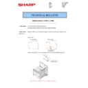
MX-6070N SIMULATION 6 – 18
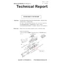
6-2
Purpose
Operation test/check
Function (Purpose)
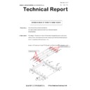
Used to check the operations of each fan
motor and its control circuit.
motor and its control circuit.
Section
Others
Operation/Procedure
1) Select the item to be operation checked with the touch panel
1) Select the item to be operation checked with the touch panel
key.
2) Press [EXECUTE] key.
The selected load performs the operation.
When [EXECUTE] key is pressed, the operation is terminated.
Press [ALL] key to select all the fans collectively.
When [EXECUTE] key is pressed, the operation is terminated.
Press [ALL] key to select all the fans collectively.
Load operation check method:
The load operation is checked by the operation sound. However,
there are some loads which cannot be checked with the operation
sound.
The load operation is checked by the operation sound. However,
there are some loads which cannot be checked with the operation
sound.
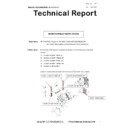
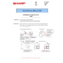
6-3
Purpose
Operation test/check
Function (Purpose)
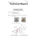
Used to check the operations of the trans-
port unit and the control circuit.
port unit and the control circuit.
Section
Process (Transport)
Operation/Procedure
1) Select the operation mode with the mode select button.
1) Select the operation mode with the mode select button.
2) When [EXECUTE] key is pressed, the operation of the mode
selected in 1) is performed.
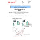
6-4
Purpose
Operation test/check
Function (Purpose)
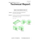
Used to check the cleaning operation of the
main charger
main charger
Section
Process
Operation/Procedure
1)
1)
Select the items to be checked with the touch panel key
2)
Press [EXECUTE] key
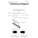
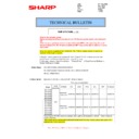
6-6
Purpose
Operation test/check
Function (Purpose)
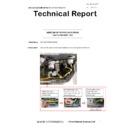
Used to perform fusing pressure release
and applying, and to check the operations
of the control circuits.
and applying, and to check the operations
of the control circuits.
Section
Fusing
Operation/Procedure
1)
1)
Press [FUSER] key to highlight it.
2)
Press [EXECUTE] key, and fusing pressure applying and fus-
ing pressure release are repeated.
ing pressure release are repeated.
During this period, the status of the fusing roller pressure is dis-
played.
played.
6-90
Purpose
Setting
Function (Purpose)
Used to reset the machine to the factory
setting. (The scanner is set to the lock
enable position)
setting. (The scanner is set to the lock
enable position)
Section
Scanner
Operation/Procedure
1)
1)
Press [EXECUTE] key.
The scanner is shifted to the lock enable position and stopped.
The scanner is shifted to the lock enable position and stopped.
7
7-1
Purpose
Setting
Function (Purpose)
Used to set the operating conditions of
aging.
aging.
Section
Others
Operation/Procedure
1)
1)
Select an item to be set with the touch panel key.
2)
Press [EXECUTE] key.
The machine is rebooted in the aging mode.
The machine is rebooted in the aging mode.
The aging operation condition set by this mode is maintained here-
after unless the power is turned off or the setting is changed.
after unless the power is turned off or the setting is changed.
Display
Content
FUFM
Fusing cooling fan
POFM2
Paper exit cooling fan
PROFM1
Process fan 1
PROFM2
Process fan 2
PSFM
Power cooling fan
Mode select button
Content
TC1
Primary transfer (normal rotation)
TC1_R
Primary transfer (reverse rotation)
TC2
Secondary transfer
Mode
select
button
Mode
display
Content
NOTE
TC1
BLACK
Monochrome
mode position
mode position
Black mode position -> Color
mode position -> Drum
separation position -> (Black
mode position)
(Repeated in this sequence.)
mode position -> Drum
separation position -> (Black
mode position)
(Repeated in this sequence.)
COLOR
Color mode
position
position
FREE
Non-transport
position
position
TC1_R
BLACK
Monochrome
mode position
mode position
Black mode position -> Drum
separation position -> Color
mode position -> (Black mode
position) (Repeated in this
sequence.)
separation position -> Color
mode position -> (Black mode
position) (Repeated in this
sequence.)
FREE
Non-transport
position
position
COLOR
Color mode
position
position
TC2
PRINT
Print position
Print position -> Drum
separation position
(Repeated in this sequence)
separation position
(Repeated in this sequence)
FREE
Non-transport
position
position
MC (K) COUNT
Main charger cleaner operation check
MC (C) COUNT
MC (M) COUNT
MC (Y) COUNT
ALL
MC (M) COUNT
MC (Y) COUNT
ALL
All color
PRINT
Fusing pressure
applying
applying
Fusing pressure applying -> Fusing
pressure release -> (Fusing pressure
applying) The operation is repeated.
pressure release -> (Fusing pressure
applying) The operation is repeated.
FREE
Fusing pressure
release
release
AGING
Aging operation setup
INTERVAL
Intermittent operation setting
MX-6070N SIMULATION 6 – 19
7-6
Purpose
Setting
Function (Purpose)
Used to set the operating intermittent aging
cycle.
cycle.
Section
Operation/Procedure
1) Enter the intermittent aging operation cycle (unit: sec) with 10-
1) Enter the intermittent aging operation cycle (unit: sec) with 10-
key.
2) Press [OK] key.
The time entered in procedure 1) is set.
* The interval time that can be set is 1 to 900 (sec).
* The interval time that can be set is 1 to 900 (sec).
The aging operation condition set by this mode is maintained here-
after unless the power is turned off or the setting is changed.
after unless the power is turned off or the setting is changed.
7-8
Purpose
Operation display
Function (Purpose)
Used to display the warm-up time.
Section
Operation/Procedure
Press [EXECUTE] key.
Counting of the warm-up time is started and the time required for
warm-up is displayed
* Interruption of counting by pressing [EXECUTE] key is inhibited.
Press [EXECUTE] key.
Counting of the warm-up time is started and the time required for
warm-up is displayed
* Interruption of counting by pressing [EXECUTE] key is inhibited.
7-9
Purpose
Operation test/check
Function (Purpose)
Color setting in the color copy test mode
(Used to check the copy operation and the
image quality for each color).
(Used to check the copy operation and the
image quality for each color).
Section
Operation/Procedure
1) Select the copy color with the touch panel key.
1) Select the copy color with the touch panel key.
(Two or more colors can be selected.)
The key of the selected color is highlighted.
The key of the selected color is highlighted.
2) Press [EXECUTE] key.
Copying is performed with the selected color.
When [CLOSE] key is pressed, the display goes into the copy oper-
ation menu in the simulation mode.
ation menu in the simulation mode.
7-12
Purpose
Operation test/check
Function (Purpose)
The document reading number of sheets
setting (for aging operation)
setting (for aging operation)
Section
SPF
Operation/Procedure
1)
1)
Set document reading quantity with 10-key.
(Setting range:0 - 255)
(Setting range:0 - 255)
2)
Press [OK] key. The set value is saved.
The aging operation condition set by this mode is maintained here-
after unless the power is turned off or the setting is changed.
after unless the power is turned off or the setting is changed.
8
8-1
Purpose
Operation test/check/adjustment
Function (Purpose)
Used to check and adjust the operations of
the developing voltage in each print mode
and the control circuit.
* When the middle speed is adjusted, the
low speed are also adjusted simultane-
ously.
the developing voltage in each print mode
and the control circuit.
* When the middle speed is adjusted, the
low speed are also adjusted simultane-
ously.
Section
Process (Developing)
Operation/Procedure
1)
1)
Select a speed with [MIDDLE] and [LOW] keys on the touch
panel.
panel.
2)
Select a target item to be adjusted with scroll keys.
3)
Enter the setting value with 10-key. (The value specified on the
label of the high voltage PWB must be entered.)
* When the r s key is pressed, the setting value of each item
label of the high voltage PWB must be entered.)
* When the r s key is pressed, the setting value of each item
can be changed with 1up (1down) collectively.
4)
Press [OK] key. Press [OK] key. The set value is saved.
MISFEED DISABLE
JAM detection ignoring setting
FUSING DISABLE
Fusing unit ignoring setting
WARMUP DISABLE
Warming up ignoring setting
DV CHECK DISABLE
Developing unit ignoring setting
SHADING DISABLE
Shading correction operation omitting setting
CCD GAIN FREE
CCD gain adjustment omitting setting
K
Setup/cancel of black
C
Setup/cancel of cyan
M
Setup/cancel of magenta
Y
Setup/cancel of yellow
Item/Display (Mode)
Content
Adjustment
range
Actual
voltage
MIDDLE
A
MIDDLE
SPEED
DVB_K
SPEED
DVB_K
Developing
bias voltage
(Middle
speed mode)
bias voltage
(Middle
speed mode)
K
0 - 600
–450V
+/- 5V
B
MIDDLE
SPEED
DVB_C
SPEED
DVB_C
Developing
bias voltage
(Middle
speed mode)
bias voltage
(Middle
speed mode)
C
0 - 600
–450V
+/- 5V
C
MIDDLE
SPEED
DVB_M
SPEED
DVB_M
Developing
bias voltage
(Middle
speed mode)
bias voltage
(Middle
speed mode)
M
0 - 600
–450V
+/- 5V
D
MIDDLE
SPEED
DVB_Y
SPEED
DVB_Y
Developing
bias voltage
(Middle
speed mode)
bias voltage
(Middle
speed mode)
Y
0 - 600
–450V
+/- 5V
LOW
A
LOW
SPEED
DVB_K
SPEED
DVB_K
Developing
bias voltage
(Low speed
mode)
bias voltage
(Low speed
mode)
K
0 - 600
–450V
+/- 5V
B
LOW
SPEED
DVB_C
SPEED
DVB_C
Developing
bias voltage
(Low speed
mode)
bias voltage
(Low speed
mode)
C
0 - 600
-450V
±5V
C
LOW
SPEED
DVB_M
SPEED
DVB_M
Developing
bias voltage
(Low speed
mode)
bias voltage
(Low speed
mode)
M
0 - 600
-450V
±5V
D
LOW
SPEED
DVB_Y
SPEED
DVB_Y
Developing
bias voltage
(Low speed
mode)
bias voltage
(Low speed
mode)
Y
0 - 600
-450V
±5V
MX-6070N SIMULATION 6 – 20
8-2
Purpose
Operation test/check/adjustment
Function (Purpose)
Used to check and adjust the operation of
the main charger grid voltage in each
printer mode and the control circuit.
* When the middle speed is adjusted, the
low speed are also adjusted simultane-
ously.
the main charger grid voltage in each
printer mode and the control circuit.
* When the middle speed is adjusted, the
low speed are also adjusted simultane-
ously.
Section
Process (Charging)
Operation/Procedure
1) Select a speed with [MIDDLE] and [LOW] keys on the touch
1) Select a speed with [MIDDLE] and [LOW] keys on the touch
panel.
2) Select a target item to be adjusted with scroll keys.
3) Enter the adjustment value with 10-key. (The value specified
3) Enter the adjustment value with 10-key. (The value specified
on the label of the high voltage PWB must be entered.)
* When the r s key is pressed, the setting value of each item
* When the r s key is pressed, the setting value of each item
can be changed with 1up (1down) collectively.
4) Press [OK] key. The set value is saved.
8-6
Purpose
Operation test/check/adjustment
Function (Purpose)
Used to check and adjust the operation of
the transport voltage and the control circuit.
the transport voltage and the control circuit.
Section
Process (Transport)
Operation/Procedure
1) Select a target item to be adjusted with scroll keys.
2) Enter the set value with 10-key.
1) Select a target item to be adjusted with scroll keys.
2) Enter the set value with 10-key.
Enter the default value specified on the following list.
3) Press [OK] key. The set value is saved.
Item/Display (Mode)
Content
Adjustment
range
Actual
voltage
MIDDLE
A
MIDDLE
SPEED
GB_K
SPEED
GB_K
Main charger
grid voltage
(Middle
speed mode)
grid voltage
(Middle
speed mode)
K
50 - 850
-630V
±5V
B
MIDDLE
SPEED
GB_C
SPEED
GB_C
Main charger
grid voltage
(Middle
speed mode)
grid voltage
(Middle
speed mode)
C
50 - 850
-630V
±5V
C
MIDDLE
SPEED
GB_M
SPEED
GB_M
Main charger
grid voltage
(Middle
speed mode)
grid voltage
(Middle
speed mode)
M
50 - 850
-630V
±5V
D
MIDDLE
SPEED
GB_Y
SPEED
GB_Y
Main charger
grid voltage
(Middle
speed mode)
grid voltage
(Middle
speed mode)
Y
50 - 850
-630V
±5V
LOW
A
LOW
SPEED
GB_K
SPEED
GB_K
Main charger
grid voltage
(Low speed
mode)
grid voltage
(Low speed
mode)
K
50 - 850
-598V
±5V
B
LOW
SPEED
GB_C
SPEED
GB_C
Main charger
grid voltage
(Low speed
mode)
grid voltage
(Low speed
mode)
C
50 - 850
-598V
±5V
C
LOW
SPEED
GB_M
SPEED
GB_M
Main charger
grid voltage
(Low speed
mode)
grid voltage
(Low speed
mode)
M
50 - 850
-598V
±5V
D
LOW
SPEED
GB_Y
SPEED
GB_Y
Main charger
grid voltage
(Low speed
mode)
grid voltage
(Low speed
mode)
Y
50 - 850
-598V
±5V
Item/Display
Content
Setting
range
Default
value
A
TC1 LOW SPEED CL K
Primary transfer bias
adjustment value
adjustment value
Color
K
Low speed
0 - 255
85
B
TC1 MIDDLE SPEED CL K
Middle speed
0 - 255
106
C
TC1 LOW SPEED CL C
C
Low speed
0 - 255
85
D
TC1 MIDDLE SPEED CL C
Middle speed
0 - 255
106
E
TC1 LOW SPEED CL M
M
Low speed
0 - 255
85
F
TC1 MIDDLE SPEED CL M
Middle speed
0 - 255
106
G
TC1 LOW SPEED CL Y
Y
Low speed
0 - 255
85
H
TC1 MIDDLE SPEED CL Y
Middle speed
0 - 255
106
I
TC1 LOW SPEED BW K
Monochrome
K
Low speed
0 - 255
85
J
TC1 MIDDLE SPEED BW K
Middle speed
0 - 255
106
K
TC2 PLAIN CL SPX
Secondary transfer bias
adjustment value
adjustment value
Color
Standard
paper
<Middle speed>
paper
<Middle speed>
Front surface
0 - 255
96
L
TC2 PLAIN CL DPX
Back surface
0 - 255
96
M
TC2 PLAIN BW SPX
Monochrome
Front surface
0 - 255
96
N
TC2 PLAIN BW DPX
Back surface
0 - 255
96
O
TC2 HEAVY1 CL SPX
Color
Heavy paper
1<106 -176g/m
1<106 -176g/m
2
>
<Low speed >
Front surface
0 - 255
90
P
TC2 HEAVY1 CL DPX
Back surface
0 - 255
96
Q
TC2 HEAVY1 BW SPX
Monochrome
Front surface
0 - 255
90
R
TC2 HEAVY1 BW DPX
Back surface
0 - 255
96
S
TC2 HEAVY2 CL SPX
Color
Heavy paper 2
<177 - 220g/m
<177 - 220g/m
2
>
<Low speed >
Front surface
0 - 255
90
T
TC2 HEAVY2 CL DPX
Back surface
0 - 255
96
U
TC2 HEAVY2 BW SPX
Monochrome
Front surface
0 - 255
90
V
TC2 HEAVY2 BW DPX
Back surface
0 - 255
96
MX-6070N SIMULATION 6 – 21
8-10
Purpose
Operation test/check/adjustment
Function (Purpose)
Used to check and adjust the operation of
the main charger total current output in
each printer mode and the control circuit.
the main charger total current output in
each printer mode and the control circuit.
Section
Process (Charging)
Operation/Procedure
1) Select a target item of setting with scroll key on the touch
1) Select a target item of setting with scroll key on the touch
panel.
2) Enter the set value with 10-key.
3) Press [OK] key. (The set value is saved.)
3) Press [OK] key. (The set value is saved.)
W
TC2 HEAVY3 CL SPX
Secondary transfer bias
adjustment value
adjustment value
Color
Heavy paper 3
<221- 256g/ m
<221- 256g/ m
2
>
<Low speed>
Front surface
0 - 255
90
X
TC2 HEAVY3 CL DPX
Back surface
0 - 255
96
Y
TC2 HEAVY3 BW SPX
Monochrome
Front surface
0 - 255
90
Z
TC2 HEAVY3 BW DPX
Back surface
0 - 255
96
AA
TC2 HEAVY4 CL
Color
Heavy paper 4 <257 - 300g/m
2
>
<Low speed >
0 - 255
90
AB
TC2 HEAVY4 BW
Monochrome
0 - 255
90
AC
TC2 OHP CL
Color
OHP <Low speed >
0 - 255
103
AD
TC2 OHP BW
Monochrome
0 - 255
103
AE
TC2 ENVELOPE CL
Color
Envelope <Low speed >
0 - 255
90
AF
TC2 ENVELOPE BW
Monochrome
0 - 255
90
AG
TC2 THIN CL
Color
Thin paper <Low speed >
0 - 255
96
AH
TC2 THIN BW
Monochrome
0 - 255
96
AI
TC2 GLOSSY PAPER CL
Color
Gross paper <Low speed >
0 - 255
90
AJ
TC2 GLOSSY PAPER BW
Monochrome
0 - 255
90
AK
TC2 EMBOSS CL
Color
Embossed paper <Low speed >
0 - 255
90
AL
TC2 EMBOSS BW
Monochrome
0 - 255
90
AM
TC2 LABEL CL
Color
Label <Low speed >
0 - 255
90
AN
TC2 LABEL BW
Monochrome
0 - 255
90
AO
TC2 FRONT EDGE LOW SPX
Front edge bias adjustment
value
value
In low speed front surface print
0 - 255
76
AP
TC2 FRONT EDGE LOW DPX
In low speed back surface print
0 - 255
69
AQ
TC2 FRONT EDGE MIDDLE SPX
In middle speed front surface print
0 - 255
83
AR
TC2 FRONT EDGE MIDDLE DPX
In middle speed back surface print
0 - 255
83
AS
TC2 BACKEND LOW SPX
Rear edge bias adjustment
value
value
In low speed front surface print
0 - 255
76
AT
TC2 BACKEND LOW DPX
In low speed back surface print
0 - 255
69
AU
TC2 BACKEND MIDDLE SPX
In middle speed front surface print
0 - 255
0
AV
TC2 BACKEND MIDDLE DPX
In middle speed back surface print
0 - 255
0
AW
TC2 INTERVAL LOW SPEED
Bias reference value between
papers
papers
In low speed print (+ pole)
0 - 255
66
AX
TC2 INTERVAL MIDDLE SPEED
In middle speed print (+ pole)
0 - 255
109
AY
TC2 CLEANING MINUS LOW SPEED
Cleaning negative bias
adjustment value
adjustment value
In low speed print (- pole)
0 - 255
54
AZ
TC2 CLEANING MINUS MIDDLE SPEED
In middle speed print (- pole)
0 - 255
62
BA
TC2 CLEANING PLUS LOW SPEED
Cleaning negative bias
adjustment value
adjustment value
In low speed print (+ pole)
0 - 255
66
BB
TC2 CLEANING PLUS MIDDLE SPEED
In middle speed print (+ pole)
0 - 255
109
BC
PTC LOW SPEED CL
PTC current adjustment value
Color
Low speed
0 - 255
109
BD
PTC MIDDLE SPEED CL
Middle speed
0 - 255
206
BE
PTC LOW SPEED BW
Monochrome
Low speed
0 - 255
109
BF
PTC MIDDLE SPEED BW
Middle speed
0 - 255
206
BG
CASE VOLT LOW CL
PTC case voltage adjustment
value
value
Color
Low speed
0 - 255
0
BH
CASE VOLT MIDDLE CL
Middle speed
0 - 255
0
BI
CASE VOLT LOW BW
Monochrome
Low speed
0 - 255
0
BJ
CASE VOLT MIDDLE BW
Middle speed
0 - 255
0
BK
DHV LOW SPEED CL SPX
Separation bias reference
value
value
Color
Low speed
Front surface
0 - 255
80
BL
DHV LOW SPEED CL DPX
Back surface
0 - 255
109
BM
DHV LOW SPEED BW SPX
Monochrome
Front surface
0 - 255
80
BN
DHV LOW SPEED BW DPX
Back surface
0 - 255
109
BO
DHV MIDLLE SPEED CL SPX
Color
Middle speed
Front surface
0 - 255
226
BP
DHV MIDLLE SPEED CL DPX
Back surface
0 - 255
226
BQ
DHV MIDLLE SPEED BW SPX
Monochrome
Front surface
0 - 255
226
BR
DHV MIDLLE SPEED BW DPX
Back surface
0 - 255
226
Item/Display
Content
Setting
range
Default
value
Item/Display
Contents
Setting
range
Default
value
Changeabl
e range
MI
DD
LE
DD
LE
A
MIDDLE
SPEED
MC_K
SPEED
MC_K
Main charger
total current K
total current K
50 - 100
70
-500 -
-1000μA
B
MIDDLE
SPEED
MC_C
SPEED
MC_C
Main charger
total current C
total current C
50 - 100
70
-500 -
-1000μA
C
MIDDLE
SPEED
MC_M
SPEED
MC_M
Main charger
total current M
total current M
50 - 100
70
-500 -
-1000μA
D
MIDDLE
SPEED
MC_Y
SPEED
MC_Y
Main charger
total current Y
total current Y
50 - 100
70
-500 -
-1000μA

