Sharp AR-M550 (serv.man12) Service Manual ▷ View online
AR-M550/M620 DETAILS OF EACH SECTION 6 - 84
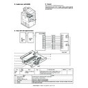
D. Maintenance and parts replacement
(1) Maintenance list
✕
: Check (Clean, replace, or adjust as necessary.)
❍
: Clean
▲
: Replace
∆
: Adjust
✩
: Lubricate
❏
: Shift position
(2) Maintenance and parts replacement
(List of Replacement Parts)
AR-M550U/M550N (PM: 250K)
When
calling
250K 500K 750K 1000K 1250K 1500K 1750K 2000K
Remark
AR-620U/M620N (PM: 300k)
300K 600K 900K 1200K 1500K 1800K 2100K 2400K
Unit name
No.
Part name
Transfer
section
section
1
Transfer belt
❍
▲
▲
▲
▲
▲
▲
▲
▲
2
Transfer roller
▲
▲
▲
▲
▲
▲
▲
▲
3
Transfer drive gear
▲
▲
▲
▲
▲
▲
▲
▲
4
Transfer cleaning roller
▲
▲
▲
▲
▲
▲
▲
▲
5
Shaft (Conduction grease)
✕
✩
✩
✩
✩
✩
✩
✩
✩
UKOG-0012QSZZ
1
2
5
5
5
3
4
5
No.
Unit
Parts
a
Transfer unit
1
Transfer drive gear
∆
2
Transfer belt
❍▲
3
Transfer auxiliary roller
4
Transfer roller
▲✕
5
Transfer roller collar
6
Transfer cleaning roller
▲
7
Transfer cleaning brush
a-2
a-6
a-1
a-5
a-5
a-3
a-4
a-7
AR-M550/M620 DETAILS OF EACH SECTION 6 - 85
a. Transfer unit
1) Open the left door unit.
2) Loosen the blue screw and open the holder to remove the transfer
unit.
a-1. Transfer drive gear
1) Remove the transfer unit. (See “a. Transfer unit” in this section)
2) Loosen the blue screw and unhook the hook lever in order to open
the transfer belt unit in the arrowed direction.
3) Remove the spring.
4) Remove the transfer belt unit in the arrowed direction.
5) Remove the transfer belt unit. (See “a-1. Transfer drive gear” in
this section)
6) Remove the ground members.
7) Remove the blue screw to remove the roller fixing members.
8) Pull out the upper transfer roller unit from the transfer belt.
9) Remove the E-ring and screw to remove the transfer drum gear.
2
1
AR-M550/M620 DETAILS OF EACH SECTION 6 - 86
a-2. Transfer belt
1) Remove the transfer unit. (See “a. Transfer unit” in this section)
2) Remove the transfer belt unit. (See “a-1. Transfer drive gear” in
this section)
3) Remove the upper transfer roller unit.
4) Pull out the transfer belt.
a-3. Transfer auxiliary roller
a-4. Transfer roller
a-5. Transfer roller collar
1) Remove the transfer unit. (See “a. Transfer unit” in this section)
2) Remove the transfer belt unit. (See “a-1. Transfer drive gear” in
this section)
3) Remove the upper transfer roller unit.
4) Remove the transfer belt. (See “a-2. Transfer belt” in this section)
5) Remove the transfer tension roller bearing to remove the transfer
roller DRG.
6) Remove the E-ring to remove the transfer roller collar.
7) Remove the E-ring to remove the transfer roller transfer roller col-
lar.
a-6. Transfer cleaning roller
1) Remove the transfer unit. (See “a. Transfer unit” in this section)
2) Remove the transfer belt unit. (See “a-1. Transfer drive gear” in
this section)
3) Remove the holder to remove the transfer cleaning roller.
a-7. Transfer cleaning brush
1) Remove the transfer unit. (See “a. Transfer unit” in this section)
2) Remove the transfer belt unit. (See “a-1. Transfer drive gear” in
this section)
3) Remove the upper transfer roller unit.
4) Remove the transfer belt. (See “a-2. Transfer belt” in this section)
5) Remove the cleaning brush.
AR-M550/M620 DETAILS OF EACH SECTION 6 - 87
[Main charger section]
A. General
The OPC drum surface is negatively charged in this section.
B. Major parts and signal functions
C. Maintenance and parts replacement
(1) Maintenance and parts replacement
(Replacement parts)
a. Main charger unit
1) Remove the front door.
2) Remove the process cover.
3) Loosen the screw.
No.
Name
Operation
1
Screen grid
Charges the OPC drum evenly. / Charges the OPC drum.
2
Saw teeth charging plate
Charges the OPC drum.
1
1
2
2
14
13
12
11
10
1
9
8
7
6
5
4
3
2
19
18
17
16
15
12
11
10
9
8
7
6
5
4
3
2
1
13
14
15
16
14
15
16
PCU PWB
MHV
THV
GB
PS-187(RD)
PS-187(YL)
Bias
PS-187(GR)
HV
CN-15
GND2
GND2
/GBPWM
/MHVREM
MHV-T
/THV+PWM
GND2
/GBPWM
/MHVREM
MHV-T
/THV+PWM
/CHV-PWM
/CHV-REM
/CHVACPWM
/CHVACREM
/DVPWM
/DVREM
HVREM
/CHV-REM
/CHVACPWM
/CHVACREM
/DVPWM
/DVREM
HVREM
CN-1
B16B-PH-K-S
(NC)
GND2
GND2
/GBPWM
/MHVREM
MHV-T
/THV+PWM
GND2
/GBPWM
/MHVREM
MHV-T
/THV+PWM
/CHV-PWM
/CHV-REM
/CHVACPWM
/CHVACREM
/DVPWM
/DVREM
HVREM
+24V1
/CHV-REM
/CHVACPWM
/CHVACREM
/DVPWM
/DVREM
HVREM
+24V1
DSW-F
DSW-F
+24V1
(NC)
(NC)
THV+REM
THV+REM
GND2
B34B-PHDSS-B
FPS-187(WH)
No.
Unit
Parts
a
Main charger unit
1
Screen grid
2
Saw teeth plate
3
MC cleaner
a-1
a
a-2
Click on the first or last page to see other AR-M550 (serv.man12) service manuals if exist.

