Sharp AR-FN5 Service Manual ▷ View online
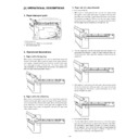
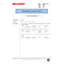
8. Attach the front and rear cabinets.
After hanging the ribs of the front and rear covers on the frames,
attach the front and rear cabinets using a screw (M4 x 10) respec-
tively.
At this time, paste the connection harness to the rear cabinet as
shown in the illustration.
attach the front and rear cabinets using a screw (M4 x 10) respec-
tively.
At this time, paste the connection harness to the rear cabinet as
shown in the illustration.
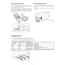
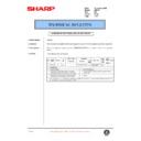
9. Attach the trays.
< 1 > Raise the paper holder lever, insert the two pawls on the rear
side of the offset tray unit to the mounting positions, and fix the
tray using the two screws (M4 x 10).
tray using the two screws (M4 x 10).
< 2 > Insert the bosses of the escape exit tray into the mounting holes
shown in the illustration and attach the tray.
[CAUTION]
When attaching the offset tray, make sure that part of the roller shaft
of the offset tray is not on the offset tray.
of the offset tray is not on the offset tray.
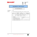
10. Mount the staple cartridge.
Remove protective paper from the cartridge.
Open the staple cover, insert the staple cartridge to the staple unit
until it clicks, and then close the staple cover.
Open the staple cover, insert the staple cartridge to the staple unit
until it clicks, and then close the staple cover.
11. Paste the staple position label.
Paste the staple position label to the document feeder.
Insert the power plug of the copier to the outlet and turn
on the main switch of the copier. Then, carry out the
following procedure.
on the main switch of the copier. Then, carry out the
following procedure.
12. Check for stapling operation.
Make three copies in the staple sort mode.
Check to see if stapling has been performed properly.
Check to see if stapling has been performed properly.
13. Check for paper delivery to the top tray.
Deliver two copies to the top tray.
If this equipment is installed together with a printer expansion kit or a
facsimile expansion kit, check the appendix of each operation manual
(key operator programs and index list output and setting).
facsimile expansion kit, check the appendix of each operation manual
(key operator programs and index list output and setting).
14. Check for paper delivery to the offset tray.
Deliver three sets from two originals to the offset tray.
Check to see if copies have been offset stacked properly.
Check to see if copies have been offset stacked properly.
Installation of staple sorter is now complete.
Screw (M4 x 10)
Screw (M4 x 10)
Front cabinet
Rear cabinet
Ribs
Ribs
Connection
harness
harness
Screw
(M4 x 10)
Top tray
Offset tray unit
Paper holder lever
pawls
Roller shaft
NG
NG
Protective paper
Staple cover
Staple cartridge
staple position label
Escape exit tray
Offset tray
Stapling position
[3] EXTERNAL VIEW AND INTERNAL STRUCTURE
1. External view
No.
Name
1
Upper tray
2
Lower tray
3
Alignment unit
1
2
3
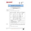
2. Sensors, motors, solenoids, etc.
1
2
3
4
5
6
7
8
9
8
9
10
11
12
13
14
15
16
17
18
19
20
21
22
23
24
25
26
27
28
29
No.
Part name
Code
Function/Operation
Type
1
Upper tray paper exit sensor
T10D
Counts down the output page, detects JAM.
Photo sensor
2
JAM process PG open/close detection
switch
switch
TCSW
Interlocks when the open/close PG of the transport section in front of
the upper stage tray is open.
the upper stage tray is open.
Micro switch
3
Escape full sensor
T1PD
Detects paper full in the upper stage tray (ESC tray).
Photo sensor
4
Paper exit roller rotation control clutch
ORCLD
Used to select whether to slow the speed of the paper exit roller upper
for the speed of the paper exit roller lower or to make it as a normal
follower roller.
for the speed of the paper exit roller lower or to make it as a normal
follower roller.
Electromagnetic
clutch
clutch
5
Main drive motor
FMM
Drives the rollers for paper transport.
Pulse motor
6
Lower tray paper exit sensor
/T20D
Counts down the output page, detects JAM.
Photo sensor
7
Paper hold solenoid
OFSLD
Presses paper onto the paper shift prevention lever of the lower stage
tray upper.
tray upper.
Solenoid
8
Paper position sensor
/T2PD
Detects the top surface of discharged paper, and detects the upper
standby position of the lift-up tray.
standby position of the lift-up tray.
Photo sensor
9
Tray offset drive motor
OFM
(+, –)
Supplies drive power to separate paper and shift the tray to the front
and the rear.
and the rear.
DC motor
10
Tray position sensor (Upper)
T2UP
Detects the lift-up tray position in combination with the tray position
sensor (lower). (Upper limit detection in the case of erroneous detection
by the paper position sensor, intermediate position detection, and full
detection)
sensor (lower). (Upper limit detection in the case of erroneous detection
by the paper position sensor, intermediate position detection, and full
detection)
Photo sensor
11
Tray position sensor (Lower)
T2DN
Detects the lift-up tray position in combination with the tray position
sensor (upper). (Upper limit detection in the case of erroneous
detection by the paper position sensor, intermediate position detection,
and full detection)
sensor (upper). (Upper limit detection in the case of erroneous
detection by the paper position sensor, intermediate position detection,
and full detection)
Photo sensor
12
Offset home position sensor
OFHP
Detects the standby position of the offset tray.
Photo sensor
13
Staple supply cover open/close
detection switch
detection switch
SCSW
Detects the staple supply cover open/close. When open, interlocks.
Micro switch
14
Lift-up motor
LUM
(+, –)
Drives the lift-up tray up and down.
DC motor
15
Lift-up drive control sensor
LUEN
Reads the encoder for control of the DC motor rotation.
Photo sensor
16
Stapler unit
17
Tray paper empty sensor
ATPD
Detects paper presence or empty on the alignment tray.
Photo sensor
18
Shutter drive solenoid
STSLD
When discharging a bundle of paper, shift the lead edge reference
plate in the paper transport direction.
plate in the paper transport direction.
Solenoid
19
Upper alignment plate drive solenoid
AJSLD
Holds paper on the alignment tray.
Solenoid
20
Side guide plate home position sensor
SDHP
Detects the home position of the width alignment members.
Photo sensor
21
Transport switch gate solenoid Right
GRSLD
Drive to sort paper into the escape transport section and the alignment
tray.
tray.
Solenoid
3. Rollers, gates, etc.
No.
Name
Function
1
Paper entry sensor
Detects paper transported from the machine.
2
Transport roller fin
Transports paper in combination with No. 8 roller.
3
Paper entry follower roller (Kick-out
sponge)
sponge)
Transports paper in combination with No. 2 roller.
4
Transport switch gate right
Selects between the escape transport (non-staple mode) and the alignment tray transport (staple
mode).
When selecting the alignment transport (staple mode), this gate drops the rear edge of paper.
mode).
When selecting the alignment transport (staple mode), this gate drops the rear edge of paper.
5
Side guide plate
Aligns paper vertically to the paper transport direction.
6
Upper alignment hold plate
Knocks paper when paper (5th page or later) comes on the alignment tray removing air or adjusting
curls.
curls.
7
Rear edge plate
Aligns paper in the paper transport direction.
8
PS upper roller (Common part)
Transports paper in combination with No. 2, 19, 20 rollers.
9
Paper empty sensor (1A71A)
Detects paper empty on the alignment tray.
10
Shutter
Serves as the paper lead edge reference for alignment of paper, and opens to allow a bundle of
paper to be transported to the paper exit port after stapling.
paper to be transported to the paper exit port after stapling.
11
Transport switch gate left
Selects between the escape tray transport and the offset tray transport.
12
PS upper roller (Common part)
Transports paper in combination with No. 13 roller.
13
Escape transport roller
Transports paper in combination with No. 12 (No. 8) roller.
14
Escape paper exit sensor
Detects paper transport to the escape tray.
15
Transports paper in combination with No. 16 roller.
16
Escape paper exit roller
Transports paper in combination with No. 15 roller.
17
Paper exit roller upper
Transports paper in combination with No. 18 roller. This roller normally follows No. 18 roller. When
discharging a stapled bundle of paper, the electromagnetic clutch turns on to make this roller a drive
roller. The bundle of paper is bent by the difference between this roller speed and the No. 18 roller
speed so that it is not caught by the preceding bundle staple.
discharging a stapled bundle of paper, the electromagnetic clutch turns on to make this roller a drive
roller. The bundle of paper is bent by the difference between this roller speed and the No. 18 roller
speed so that it is not caught by the preceding bundle staple.
18
Paper exit roller lower
Transports (discharges) paper in combination with No. 17 roller.
19
Transport drive roller fin
Transports paper in combination with No. 8 roller.
20
Paper entry roller fin
Transports paper in combination with No. 8 roller.
No.
Part name
Code
Function/Operation
Type
22
Transport switch gate solenoid Left
GLSL
Drive to sort paper into the escape paper exit port and the lift-up tray
paper exit port.
paper exit port.
Solenoid
23
Side guide plate alignment motor
SDM
Aligns paper vertically to the paper transport direction.
Pulse motor
24
Reciprocating alignment motor
BKM
Aligns paper in the paper transport direction.
Pulse motor
25
Paper entry sensor
INPD
Detects paper entry in the finisher and detects JAM. Switch trigger of
the transport switch gate right.
the transport switch gate right.
Photo sensor
26
Paper width sensor
WDPD
Make a distinction between A4 and A5R, LT and INVR. If the paper
entry sensor is ON and this sensor is OFF, it is A5R or INVR.
entry sensor is ON and this sensor is OFF, it is A5R or INVR.
Photo sensor
27
Rear edge plate drive solenoid
BKSLD
Drives the rear edge plate.
Solenoid
28
Rear edge plate home position sensor
BKHP
Detects the home position of the rear edge alignment members.
Photo sensor
29
Tray JAM process detection switch
PGSW
Interlocks when the alignment tray is opened downward in a JAM
process.
process.
Micro switch
1
2
3
20
4
5
6
2
19
7
11
9
10
16
15
14
12
13
17
18
8
8
8
Display

