Sharp AR-FN5 Service Manual ▷ View online
Digital copier option
Staple sorter
Staple sorter
MODEL
AR-FN5
[ 1 ] SPECIFICATIONS .................................................................................. 1
[ 2 ] UNPACKING AND INSTALLATION ....................................................... 2
[ 3 ] EXTERNAL VIEW AND INTERNAL STRUCTURE ................................ 5
[ 4 ] OPERATIONAL DESCRIPTIONS .......................................................... 8
[ 5 ] DISASSEMBLY AND SSEMBLY .......................................................... 13
[ 6 ] ADJUSTMENTS ................................................................................... 20
[ 7 ] MAINTENANCE.................................................................................... 22
[ 8 ] TROUBLESHOOTING.......................................................................... 23
[ 9 ] CIRCUIT DESCRIPTIONS ................................................................... 25
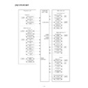
[ 10 ] OUTLINE MAP ..................................................................................... 35
[ 11 ] ELECTRICAL SECTION....................................................................... 36
CONTENTS
Parts marked with "
" are important for maintaining the safety of the set. Be sure to replace these parts with specified
ones for maintaining the safety and performance of the set.
SHARP CORPORATION
SERVICE MANUAL
[1] SPECIFICATIONS
1. Type
Installation-to-the-copier type
2. Tray
Number of trays: 2
Type:
Upper tray, normal type
Lower tray, lift-up type (with the offset function)
Lower tray, lift-up type (with the offset function)
Capacity:
Upper tray, 100 pages
Lower tray, 1,000 pages (500 pages for A4/Letter
or greater)
Lower tray, 1,000 pages (500 pages for A4/Letter
or greater)
3. Paper transport
Center reference
4. Paper exit system
Face down
5. Paper exit size
Upper tray:
A4 / A4R / A5 / A5R / B4 / B5 / B5R / A5 / 11x17 /
8.5x14 / 8.5x13 / 8.5x11 / 8.5x11R / INV / FC / OHP /
Label sheet / Second original / 16k / 16kR / 8k
8.5x14 / 8.5x13 / 8.5x11 / 8.5x11R / INV / FC / OHP /
Label sheet / Second original / 16k / 16kR / 8k
Lower tray:
A3 / A4 / A4R / B4 / B5 / B5R / 11x17 / 8.5x14 / 8.5x13 /
8.5x11 / 8.5x11R / FC / 16k / 16kR / 8k
8.5x11 / 8.5x11R / FC / 16k / 16kR / 8k
6. Paper weight
52 ~ 128g/m
2
(Upper/lower trays)
7. Paper exit full detection
Provided (Upper/lower trays)
8. Offset
Offset allowed: Lower tray
Offset quantity: 27mm
9. Paper exit job
Machine tray:
Printer, FAX, and copy output
Finisher upper tray: FAX output and interruption output
Note: The factory default is 1. Setup to 2, 3, 4 is made
by the user.
When a COPY/FAX model is set to the default
(1), an interrupt copy to the top tray is inhibited.
When a COPY/FAX model is set to the default
(1), an interrupt copy to the top tray is inhibited.
Finisher lower tray: Copy, printer output
10. Staple section
Staple allowed:
Lower tray
Binding capacity:
Max. 30 pages (80g/u or less)
Paper size:
AB series: A3, B4, A4, A4R, B5
Inch series: 11x17, 8.5x14, 8.5x13, 8.5x11, 8.5x11R
For Mainland China: A3, B4, A4, A4R, B5, 16k, 8k
Binding reference: Parallel binding at one position
Staple supply: Cartridge-type (3,000 pcs. or more)
Detection: Staple empty detection, no cartridge detec-
tion
Manual stapling: Not provided.
11. Power source
Supplied from the copier. 24V/5V/3.3V
12. Power consumption
63W (Max.)
13. External dimensions
Finisher paper exit section: 173.5(W) x 511(D) x 540(H) mm (Except
for the tray)
for the tray)
Compiler section: 562(W) x 444(D) x 109(H) mm
14. Weight
About 19kg (Finisher body 11kg, compiler section 7kg)
Note: The finisher cannot be used with the manual paper feed tray.
[2] UNPACKING AND INSTALLATION
1. Unpacking
2. Installation
If this unit is installed together with AR-SP4/RP3 or DM-SP2/RP1,
install AR-SP4/RP3 or DM-SP2/RP1 before installing this unit.
For improvement of workability, part of the description in this manual
may be modified without prior notice. In this case, refer to the service
manual.
install AR-SP4/RP3 or DM-SP2/RP1 before installing this unit.
For improvement of workability, part of the description in this manual
may be modified without prior notice. In this case, refer to the service
manual.
Remove all pieces of fixing tape and fixing materials from
the finisher.
the finisher.
·
< 1 >, to < 2 >, < 3 >, < 4 >, < 5 >, < 7 >, and < 8 > indicate tape.
·
< 6 >, < 9 >, and < 10 > indicate fixing material.
Turn off the main switch of the copier and then remove
the power plug of the copier from the outlet.
the power plug of the copier from the outlet.
1. Remove the inner cabinet from the copier.
< 1 > Pull the lock lever to the right and then pull out the rail dummy
cover to remove it.
< 2 > Remove the pawl from the exit dummy cover and remove the exit
dummy cover.
< 3 > Remove the screw and remove the rear exit cover.
< 4 > If this unit is installed together with AR-SP4/RP3 or DM-
SP2/RP1, install AR-SP4/RP3 or DM-SP2/RP1 before installing
this unit.
this unit.
2. Fit the mounting fixtures.
Cut and remove the two cut-out portions from the right cabinet of the
copier using a tool such as nippers.
(Be careful about the direction of the tool so that the cut surface is
flat.)
Fix the two mounting fixtures using two screws (M4 x 10) respectively.
copier using a tool such as nippers.
(Be careful about the direction of the tool so that the cut surface is
flat.)
Fix the two mounting fixtures using two screws (M4 x 10) respectively.
Mounting fixtures: 2 pcs.
Harness cover: 1 pc.
Staple cartridge: 1 pc.
Screws (M4 x 10): 10 pcs.
Top tray: 1 pc.
Offset tray unit: 1 pc.
Staple position label
: 1 sheet
: 1 sheet
Installation manual
: 1 sheet
: 1 sheet
Tape
Tape (wire handling)
Rail dummy cover
Exit dummy cover
Lock lever
Pawl
Rear exit cover
Screw (M3 x 10)
Paper pressure rollers
Cut-out portions
Screws (M4 x 10)
Screws (M4 x 10)
Metal fitting
Metal fitting
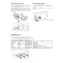
3. Remove the front and rear cabinets.
Remove the screw for each cabinet and remove the front and rear
cabinets.
cabinets.
4. Attach the exit unit.
Lower the exit unit from above the mounting fixtures so that the right
and left positioning bosses are placed into the U-shaped grooves of
the fixtures. Then, fix the front side and the rear side using a screw
(M4 x 10) respectively.
and left positioning bosses are placed into the U-shaped grooves of
the fixtures. Then, fix the front side and the rear side using a screw
(M4 x 10) respectively.
5. Attach the alignment unit.
Place the rails of the alignment unit on the guide of the copier and
push it until it stops. Then, attach it using two screws (M4 x 10).
push it until it stops. Then, attach it using two screws (M4 x 10).
6. Connect each connector
< 1 > Connect the two harnesses of the alignment unit and the staple
connector to the exit unit relay harness on the front side.
< 2 > Pull out the harnesses of the alignment unit through the hole of
the copier rear frame and connect them to the three connectors
of the finisher PWB.
of the finisher PWB.
< 3 > Connect the harness to the connector of the copier and fix it
using the screws.
7. Attach the harness cover.
Insert the rib of the harness cover into the left inner cabinet and then
hang the pawl on the right frame.
hang the pawl on the right frame.
Front cabinet
Rear cabinet
Screw (M4 x 10)
Screw (M4 x 10)
Bosses
Mounting fixtures
U-shaped groove
U-shaped groove
Rear side
Screw (M4 x 10)
Screw (M4 x 10)
Alignment unit
Right rail of
alignment unit
alignment unit
Screw (M4 x 10)
Screw (M4 x 10)
Guide
Copier guide
Rail
Pass the harness here.
Harness
Front side
Rear side
Screws
Harness
Pawl
Rib
Harness cover
(Top view)
Display

