Sharp AR-FN2 (serv.man2) Service Manual ▷ View online
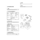
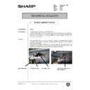
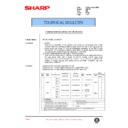
4. Attach the lock plates.
Cut out the three lock plate mounting holes on the copier using a
Phillips screwdriver or the like and remove the burrs using a flat-blade
screwdriver or the like.
Phillips screwdriver or the like and remove the burrs using a flat-blade
screwdriver or the like.
Then remove the screw from the left cabinet of the copier and secure
the lock plates to the copier as shown in the figure using screws B
(one for each plate) and positioning screws (one for each plate). (Be
careful about the orientation of the lock plates.)
the lock plates to the copier as shown in the figure using screws B
(one for each plate) and positioning screws (one for each plate). (Be
careful about the orientation of the lock plates.)
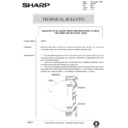
5. Connect the finisher with the copier.
Cut out the two mounting holes at the lower part of the desk (leftmost
hole and third hole from the left) using a Phillips screwdriver or the
like and remove the burrs using a flat-blade screwdriver or the like.
hole and third hole from the left) using a Phillips screwdriver or the
like and remove the burrs using a flat-blade screwdriver or the like.
Secure the mounting plate that is attached to the finisher connecting
plate to the lower part of the desk using two screws C.
plate to the lower part of the desk using two screws C.
6. Connect the finisher connector.
Cut the connector cover for connection of the finisher relay harness
connector on the copier using nippers.
connector on the copier using nippers.
Then connect the finisher relay harness connector to the connector
on the copier and secure the connector by tightening the screw on
the connector.
on the copier and secure the connector by tightening the screw on
the connector.
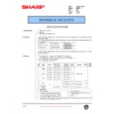
7. Check and adjust the height of the finisher.
Move the finisher toward the copier, and check and adjust the height
so that the guide pin of the copier is inserted smoothly into the
positioning hole of the finisher.
so that the guide pin of the copier is inserted smoothly into the
positioning hole of the finisher.
·
Since adjustment has been made at shipping, this adjustment
is basically not needed. If the guide pin should not be inserted
smoothly, adjust the height using the following procedure.
is basically not needed. If the guide pin should not be inserted
smoothly, adjust the height using the following procedure.
<1> Push the finisher into the copier.
Then, rotate the adjusting screw on the rear side of the finisher
lower part (Fig. 1) so that length b of the lock plate and lock
pawl on the rear side is within
lower part (Fig. 1) so that length b of the lock plate and lock
pawl on the rear side is within
±
0.5 mm in relation to length a of
the lock plate and lock pawl on the front side.
Screw
Positioning screw
Positioning screw
Screw B
Screw B
Lock plate
Lock plate
Mounting holes
Mounting holes
Screws C
Mounting plate
Connector cover
Screw
Connector
Adjusting screw
[Fig. 1]
a
b
Lock plate
Lock plate
1 – 3
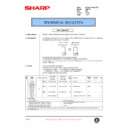
<2> Push the finisher into the copier.
At this time, check to see if the clearance between the lower
part of the finisher and the copier is approximately 1 mm (small
clearance).
part of the finisher and the copier is approximately 1 mm (small
clearance).
If the finisher touches the copier or the clearance is too large:
Adjust the clearance by rotating the adjusting screw that is attached
to the paper exit side of the lower part of the finisher (Fig. 2).
to the paper exit side of the lower part of the finisher (Fig. 2).
·
If the finisher touches the copier or the finisher is not locked:
Rotate the adjusting screw clockwise so that the clearance be-
tween the lower part of the finisher and the copier is approximately
1 mm.
tween the lower part of the finisher and the copier is approximately
1 mm.
·
If the clearance is too large:
Rotate the adjusting screw counter-clockwise so that the clearance
between the lower part of the finisher and the copier is approxi-
mately 1 mm.
between the lower part of the finisher and the copier is approxi-
mately 1 mm.
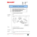
8. Stick a stapling position label.
For document cover
For SPF
For ADF/RADF
Approximately 1 mm
Adjusting screw
[Fig. 2]
Stapling position label A
Stapling position label A
Stapling position label B
1 – 4
Insert the power plug of the copier to an outlet, turn
the power switch to the "ON" position and then
perform the following procedure.
the power switch to the "ON" position and then
perform the following procedure.
Finisher operation check
·
Check the operation in the staple mode.
Make 10 copies in the staple mode and check that the copies are
stapled properly.
stapled properly.
If the copies are not stapled at this time, use the following proce-
dure to feed staples to the tip.
dure to feed staples to the tip.
1. Open the stapler cover of the finisher.
2. Remove the staple cartridge.
Raise the staple cartridge release lever of the stapler unit to re-
move the staple cartridge.
move the staple cartridge.
3. Close the stapler cover of the finisher and remove the copies.
After removing the staple cartridge, close the stapler cover of the
finisher.
finisher.
Then remove the copies from the finisher.
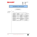
4. Check the staple cartridge.
Check that the first staple is at the STAPLE TEAR line of the
cartridge before setting the cartridge.
cartridge before setting the cartridge.
·
If the first staple does not reach the STAPLE TEAR line, pull it
to the line.
to the line.
·
If the first staple protrudes past the STAPLE TEAR line, tear
the staples and align the first staple with the line.
the staples and align the first staple with the line.
5. Set the staple cartridge.
Open the stapler cover of the finisher and set the staple cartridge
in the stapler unit.
in the stapler unit.
Insert the cartridge securely until it clicks.
Close the stapler cover.
Installation of the finisher is now complete.
STAPLE
TEAR line
TEAR line
(1)
(2)
1 – 5
Display

