Sharp AR-C330 (serv.man5) Service Manual ▷ View online
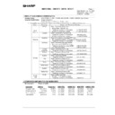
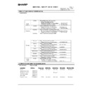
AR-C330 SIMULATION 8 - 4
10
0
Used to check the operation of the toner
motor and the control circuit. (Note)
Never execute this simulation with toner
in the toner hopper. Otherwise excessive
toner will enter the developing section.
Be sure to remove the toner from the
toner hopper.
motor and the control circuit. (Note)
Never execute this simulation with toner
in the toner hopper. Otherwise excessive
toner will enter the developing section.
Be sure to remove the toner from the
toner hopper.
Operation test/check
Image process
(Photoconductor/
Developing/Transfer/
Cleaning)
(Photoconductor/
Developing/Transfer/
Cleaning)
Developer/
Toner Hopper
Toner Hopper
Operation
14
0
Used to cancel self diag troubles H3,
H4, and H5. Inhibition of the color copy
mode operation is canceled.
H4, and H5. Inhibition of the color copy
mode operation is canceled.
Clear/Cancel (Trouble
etc.)
etc.)
Trouble
Error
15
0
Used to cancel self diag trouble U6
(Large capacity tray).
(Large capacity tray).
Clear/Cancel (Trouble
etc.)
etc.)
Paper transport
Trouble
16
0
Used to cancel self diag trouble U2.
Clear/Cancel (Trouble
etc.)
etc.)
Trouble
Error
17
0
Used to cancel self diag troubles PF
(copy inhibition command from the host
computer).
(copy inhibition command from the host
computer).
Clear/Cancel (Trouble
etc.)
etc.)
Communication unit
(TEL/LIU/MODEM etc.)
(TEL/LIU/MODEM etc.)
Trouble
Error
21
1
Used to set the maintenance cycle.
Setting
Specifications
Counter
22
1
Used to check the print count value in
each section and each operation mode.
(Used to check the maintenance timing.)
each section and each operation mode.
(Used to check the maintenance timing.)
Operation data output/
Check (Display/Print)
Check (Display/Print)
Counter
2
Used to check the total misfeed count
and the total trouble count. (If the
misfeed count is considerably great, it
may be judged as necessary to repair. By
dividing this count by the total count, the
misfeed rate can be obtained.)
and the total trouble count. (If the
misfeed count is considerably great, it
may be judged as necessary to repair. By
dividing this count by the total count, the
misfeed rate can be obtained.)
Operation data output/
Check (Display/Print)
Check (Display/Print)
Trouble
3
Used to check misfeed positions and the
misfeed count of each position. (If the
misfeed count is considerably great, it
may be judged as necessary to repair.)
(Other sections than RADF section)
misfeed count of each position. (If the
misfeed count is considerably great, it
may be judged as necessary to repair.)
(Other sections than RADF section)
Operation data output/
Check (Display/Print)
Check (Display/Print)
Trouble
Misfeed
4
Used to check the total trouble (self
diag) history.
diag) history.
Operation data output/
Check (Display/Print)
Check (Display/Print)
Trouble
5
Used to check the ROM version of
each unit (section).
each unit (section).
Others
Software
6
Used to print the setting and
adjustment data list.
adjustment data list.
Operation data output/
Check (Display/Print)
Check (Display/Print)
Operation
7
Used to display the key operator code.
(Used when the customer forgets the
key operator code.)
(Used when the customer forgets the
key operator code.)
User data output/Check
(Display/Print)
(Display/Print)
Data
User data
8
Used to check the number of uses of
the staple, and the RADF.
the staple, and the RADF.
Operation data output/
Check (Display/Print)
Check (Display/Print)
Counter
9
Used to check the number of uses (print
quantity) of each paper feed section.
quantity) of each paper feed section.
Operation data output/
Check (Display/Print)
Check (Display/Print)
Paper transport
Counter
10
Used to check the system configuration
(option, internal hardware).
(option, internal hardware).
Operation data output/
Check (Display/Print)
Check (Display/Print)
Specifications
Options
12
Used to check the misfeed positions
and the number (history) of misfeed at
each position. (If the misfeed count is
considerably great, it may be judged as
necessary to repair.)
and the number (history) of misfeed at
each position. (If the misfeed count is
considerably great, it may be judged as
necessary to repair.)
Operation data output/
Check (Display/Print)
Check (Display/Print)
RADF
Trouble
Misfeed
24
1
Used to clear the misfeed counter, the
misfeed history, the trouble counter,
and the trouble history. (After
completion of maintenance, the
counters are cleared.)
misfeed history, the trouble counter,
and the trouble history. (After
completion of maintenance, the
counters are cleared.)
Data clear
Memory
Counter
2
Used to clear the data of the number of
uses (print quantity) of each paper feed
section.
uses (print quantity) of each paper feed
section.
Data clear
Paper transport
Counter
Paper feed
3
Used to clear the data of the number of
uses of the stapler, the RADF, and the
scanner., Data clear
uses of the stapler, the RADF, and the
scanner., Data clear
Counter
4
Used to reset the maintenance counter. Data clear
Counter
Maintenance
5
Used to reset the developer counter.
(The developer counter of the installed
DV unit is reset.)
(The developer counter of the installed
DV unit is reset.)
Data clear
Image process
(Photoconductor/
Developing/Transfer/
Cleaning)
(Photoconductor/
Developing/Transfer/
Cleaning)
Developer/
Toner Hopper
Toner Hopper
Counter
Developer
6
Used to clear the copy counters.
Data clear
Counter
7
Used to clear the OPC drum
(membrane decrease) correction
counter. (Performed when the OPC
drum is replaced.)
(membrane decrease) correction
counter. (Performed when the OPC
drum is replaced.)
Data clear
Image process
(Photoconductor/
Developing/Transfer/
Cleaning)
(Photoconductor/
Developing/Transfer/
Cleaning)
Photo
conductor
conductor
Counter
Photo conductor
Code
Function (Purpose)
Purpose
Section
Item
Main
Sub
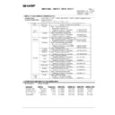
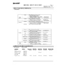
AR-C330 SIMULATION 8 - 5
24
8
Used to clear the waste toner counter
in the transfer section.
in the transfer section.
Data clear
Image process
(Photoconductor/
Developing/Transfer/
Cleaning)
(Photoconductor/
Developing/Transfer/
Cleaning)
Copy
Counter
9
Printer/Other counter clear
Data clear
Printer
Counter
25
1
Used to check the operation of the main
drive (excluding the scanner section) and
the toner density sensor. (The toner
density sensor output can be monitored.)
drive (excluding the scanner section) and
the toner density sensor. (The toner
density sensor output can be monitored.)
Operation test/check
Image process
(Photoconductor/
Developing/Transfer/
Cleaning)
(Photoconductor/
Developing/Transfer/
Cleaning)
Developer/
Toner Hopper
Toner Hopper
Operation
2
Used to make the initial setup
(automatic adjustment) of toner density
when replacing developer.
(automatic adjustment) of toner density
when replacing developer.
Setting
Image process
(Photoconductor/
Developing/Transfer/
Cleaning)
(Photoconductor/
Developing/Transfer/
Cleaning)
Developer/
Toner Hopper
Toner Hopper
26
1
Used to make option setup. (When
installing an option,this simulation is
used to setup for that option (software).
installing an option,this simulation is
used to setup for that option (software).
Setting
Specifications
Options
2
1) Used to set the paper size of the
large capacity tray. (When the
paper size is changed, the software
setup must be changed
accordingly with this simulation.)
paper size is changed, the software
setup must be changed
accordingly with this simulation.)
2) Used to detect 8.5 x 13 (INCH
Series) paper or documents and to
set the display mode. (All paper
feed modes)
set the display mode. (All paper
feed modes)
3) Used to set the display form of the
paper kind in the manual paper
feed mode.
feed mode.
Setting
Paper transport
Specifications
3
Used to set the auditor specification
mode. Setting must be made according
to the use conditions of the auditor.
mode. Setting must be made according
to the use conditions of the auditor.
Setting
Auditor
Specifications
5
Used to set the count mode of the total
counter, the developer counter, and the
maintenance counter.
counter, the developer counter, and the
maintenance counter.
Setting
Specifications
Counter
6
1) Used to set the specifications
(paper, fixed copy magnification
ratio, machine operations in case
of an image (process) correction
error) according to the destination.
ratio, machine operations in case
of an image (process) correction
error) according to the destination.
Setting
Specifications
Destination
18
Used to set YES/NO of toner save
operation. (This simulation is valid only for
Japan and UK versions. It depends on Sim
26-6 (Destination) setting. For the other
destinations, the same setting can be
made by the user program P22. (Effective
only in the monochrome copy mode)
operation. (This simulation is valid only for
Japan and UK versions. It depends on Sim
26-6 (Destination) setting. For the other
destinations, the same setting can be
made by the user program P22. (Effective
only in the monochrome copy mode)
Setting
Specifications Operation mode
(Common)
22
Used to set the specification
(language) for the destination.
(language) for the destination.
Setting
Specifications
Language
28
Used to set the AC power voltage. (For
control of the fusing section heater lamp)
control of the fusing section heater lamp)
Setting
Power supply (DC/AC/
High)
High)
Operation
30
Used to set the CE mark complying
operation mode. (Conforms to the soft
start when driving the fusing heater lamp.)
operation mode. (Conforms to the soft
start when driving the fusing heater lamp.)
Setting
Fixing (Fusing)
Specifications
Operation mode
(Common)
(Common)
32
Used to set the fan rotating speed. (low
speed)
speed)
Setting
Operation
35
Used to set whether the trouble history
display by SIM 22-4 is displayed as one
trouble or as the accumulated number of
continuous troubles when two or more
troubles of same kind occur continuously.
display by SIM 22-4 is displayed as one
trouble or as the accumulated number of
continuous troubles when two or more
troubles of same kind occur continuously.
Setting
Specifications
52
Used to set YES/NO of count up of non-
copy paper (cover or insertion paper).
copy paper (cover or insertion paper).
Setting
Specification
Operation mode
53
Used by the user to set Enable/Disable
auto color calibration (auto adjustment
of color balance and density)
auto color calibration (auto adjustment
of color balance and density)
Setting
Specifications
Operation mode
55
Used to select the gamma
characteristics in the color copy mode.
characteristics in the color copy mode.
Setting
ICU
Operation
56
Used to set Disable/Enable of paper
type setting of key operation P67 and
P68.
type setting of key operation P67 and
P68.
Setting
Code
Function (Purpose)
Purpose
Section
Item
Main
Sub
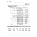
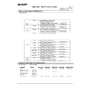
AR-C330 SIMULATION 8 - 6
27
1
Used to set the specifications for
operations in case of communication
trouble between the host computer and
MODEM (machine side). (When
communication trouble occurs between
the host computer MODEM and the
machine, the self diag display (U7-00)
is printed and setting for inhibition of
print or not is made.)
operations in case of communication
trouble between the host computer and
MODEM (machine side). (When
communication trouble occurs between
the host computer MODEM and the
machine, the self diag display (U7-00)
is printed and setting for inhibition of
print or not is made.)
Setting
Communication unit
(TEL/LIU/MODEM etc.)
(TEL/LIU/MODEM etc.)
Specifications
Operation mode
(Common)
(Common)
2
Used to set or change the host
computer/MODEM number. (This
setting is required when a
communication is made between the
copier and the computer through
MODEM.)
computer/MODEM number. (This
setting is required when a
communication is made between the
copier and the computer through
MODEM.)
Setting
Communication unit
(TEL/LIU/MODEM etc.)
(TEL/LIU/MODEM etc.)
Data
User data
3
Used to set and change the ID
numbers of the copier, the host
computer/MODEM. (This setting is
required when a communication is
made between the copier and the
computer through MODEM.)
numbers of the copier, the host
computer/MODEM. (This setting is
required when a communication is
made between the copier and the
computer through MODEM.)
Setting
Communication unit
(TEL/LIU/MODEM etc.)
(TEL/LIU/MODEM etc.)
Data
Communication
4
Used to enter the service start time and
service end time for management of
servicing. (The data can be checked
with the host computer.)
service end time for management of
servicing. (The data can be checked
with the host computer.)
Setting
Communication unit
(TEL/LIU/MODEM etc.)
(TEL/LIU/MODEM etc.)
Data
Communication
5
Used to enter the machine TAG No.
(This function allows to check the TAG
No. of the machine with the host
computer.)
(This function allows to check the TAG
No. of the machine with the host
computer.)
Setting
Communication unit
(TEL/LIU/MODEM etc.)
(TEL/LIU/MODEM etc.)
Data
User data
6
Used to set ON/OFF of service call
sending to the service center by use of
RIC when trouble occurred in the
machine. (The service call is not sent
automatically, but sent manually.)
sending to the service center by use of
RIC when trouble occurred in the
machine. (The service call is not sent
automatically, but sent manually.)
Setting
Communication unit
(TEL/LIU/MODEM etc.)
(TEL/LIU/MODEM etc.)
Specifications
Others
29
4
Setting
Memory
Counter
30
1
Used to check the operation of sensors
and detectors in the paper feed, paper
transport, paper exit sections and the
related circuits.
and detectors in the paper feed, paper
transport, paper exit sections and the
related circuits.
Operation test/check
Operation
2
Used to check the operation of sensors
and detectors in the paper feed section
and the related circuits. (The operation
of the paper feed sensors and
detectors can be monitored with the
LCD display.)
and detectors in the paper feed section
and the related circuits. (The operation
of the paper feed sensors and
detectors can be monitored with the
LCD display.)
Operation test/check
Paper transport
Operation
33
1
Used to check the operation of the card
reader and the sensors and the related
circuits. (The card reader sensor
operation can be monitored with the
LCD display.)
reader and the sensors and the related
circuits. (The card reader sensor
operation can be monitored with the
LCD display.)
Operation test/check
Others
Operation
40
1
Used to check the operation of the
manual feed tray paper size detector
and the related circuit. (The operation
of the manual feed tray paper size
detector can be monitored with the
LCD display.)
manual feed tray paper size detector
and the related circuit. (The operation
of the manual feed tray paper size
detector can be monitored with the
LCD display.)
Operation test/check
Paper transport
Operation
2
Used to adjust the manual feed tray
paper width detector detection level.
paper width detector detection level.
Adjustment
Paper transport
Operation
4
Used to check the OHP sensor and its
control circuit.
control circuit.
Operation test/check
Paper transport
Operation
5
Used to adjust the detection level of the
OHP sensor.
OHP sensor.
Adjustment
Paper feed
Operation
6
Used to set the OHP sensor
adjustment parameter.
adjustment parameter.
Setting
Paper feed
Operation
41
1
Used to check the operation of the
document size sensor and the related
circuit. (The operation of the document
size sensor can be monitored with the
LCD display.)
document size sensor and the related
circuit. (The operation of the document
size sensor can be monitored with the
LCD display.)
Operation test/check/
Operation data Output/
Check (Display/Print)
Operation data Output/
Check (Display/Print)
Others
Operation
2
Used to adjust the document size
sensor detection level.
sensor detection level.
Adjustment
Others
Operation
3
Used to check the operation of the
document size sensor and the related
circuit. (The document size sensor
output level can be monitored with the
LCD display.)
document size sensor and the related
circuit. (The document size sensor
output level can be monitored with the
LCD display.)
Operation test/check
Others
Operation
Code
Function (Purpose)
Purpose
Section
Item
Main
Sub
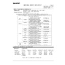
AR-C330 SIMULATION 8 - 7
43
1
Used to set the fusing temperature in
each operation mode.
each operation mode.
Setting
Fixing (Fusing)
Operation
7
Used to adjust the fusing oil supply
amount. (Adjustment of oil motor ON
time and oil motor ON interval)
amount. (Adjustment of oil motor ON
time and oil motor ON interval)
Adjustment
Fixing (Fusing)
Operation
44
1
Used to set enable/disable of
correction operations in the image
forming (process) section.
correction operations in the image
forming (process) section.
Setting
Image process
(Photoconductor/
Developing/Transfer/
Cleaning)
(Photoconductor/
Developing/Transfer/
Cleaning)
Operation
2
Used to check the operation of the
temperature sensor and the humidity
sensor for correction of the image
process section. (The sensor detection
level can be monitored.)
temperature sensor and the humidity
sensor for correction of the image
process section. (The sensor detection
level can be monitored.)
Operation test/check
Operation
4
Used to set the target image
(reference) density level in correction
(process correction) operations in the
image forming section.
(reference) density level in correction
(process correction) operations in the
image forming section.
Setting
Image process
(Photoconductor/
Developing/Transfer/
Cleaning)
(Photoconductor/
Developing/Transfer/
Cleaning)
Picture quality Density
5
Used to set the correction start
developing bias voltage in correction
(process correction) operations in the
image forming section.
developing bias voltage in correction
(process correction) operations in the
image forming section.
Setting
Image process
(Photoconductor/
Developing/Transfer/
Cleaning)
(Photoconductor/
Developing/Transfer/
Cleaning)
Developer/
Toner Hopper
Toner Hopper
Operation
6
Used to forcibly execute the image
forming section correction (process
correction).
forming section correction (process
correction).
Operation test/check
Image process
(Photoconductor/
Developing/Transfer/
Cleaning)
(Photoconductor/
Developing/Transfer/
Cleaning)
Operation
9
Used to check the data on the image
forming section correction (process
correction) (corrected main charger
grid voltage, the developing bias
voltage, the laser power, etc, in each
print mode). (This simulation allows to
check if the correction operation is
performed normally.)
forming section correction (process
correction) (corrected main charger
grid voltage, the developing bias
voltage, the laser power, etc, in each
print mode). (This simulation allows to
check if the correction operation is
performed normally.)
Operation data output/
Check (Display/Print)
Check (Display/Print)
Image process
(Photoconductor/
Developing/Transfer/
Cleaning)
(Photoconductor/
Developing/Transfer/
Cleaning)
Data
Operation data
(Machine
condition)
(Machine
condition)
12
Used to check the toner image patch
density data in the image forming
section correction (process correction).
This simulation allows to check if the
correction operation is performed
normally.)
density data in the image forming
section correction (process correction).
This simulation allows to check if the
correction operation is performed
normally.)
Operation data output/
Check (Display/Print)
Check (Display/Print)
Image process
(Photoconductor/
Developing/Transfer/
Cleaning)
(Photoconductor/
Developing/Transfer/
Cleaning)
Data
Operation data
(Machine
condition)
(Machine
condition)
13
Used to adjust the image density
sensor (for color) sensitivity (gain).
sensor (for color) sensitivity (gain).
Adjustment
Image process
(Photoconductor/
Developing/Transfer/
Cleaning)
(Photoconductor/
Developing/Transfer/
Cleaning)
Copy
14
Used to monitor the output level of the
fusing temperature sensor, the
machine temperature sensor, and the
humidity sensor.
fusing temperature sensor, the
machine temperature sensor, and the
humidity sensor.
Operation data output/
Check (Display/Print)
Check (Display/Print)
Others
16
Used to check the toner concentration
correction result. (This simulation
allows to check if correction is
executed properly or not.)
correction result. (This simulation
allows to check if correction is
executed properly or not.)
Operation data output/
Check (Display/Print)
Check (Display/Print)
Image process
(Photoconductor/
Developing/Transfer/
Cleaning)
(Photoconductor/
Developing/Transfer/
Cleaning)
Developer/
Toner Hopper
Toner Hopper
Data
Operation data
(Machine
condition)
(Machine
condition)
21
Used to store color balance adjustment
data. (Half tone image correction initial
setting) (After execution of color
balance adjustment with SIM 46-21,
this simulation must be executed.)
data. (Half tone image correction initial
setting) (After execution of color
balance adjustment with SIM 46-21,
this simulation must be executed.)
Setting
Picture quality
22
Used to check each color toner patch
image density UITU in half tone image
forming section correction (process
correction). (This simulation allows to
check if correction operation is
performed normally.)
image density UITU in half tone image
forming section correction (process
correction). (This simulation allows to
check if correction operation is
performed normally.)
Operation data output/
Check (Display/Print)
Check (Display/Print)
Image process
(Photoconductor/
Developing/Transfer/
Cleaning)
(Photoconductor/
Developing/Transfer/
Cleaning)
Data
Operation data
(Machine
condition)
(Machine
condition)
23
Used to adjust the image density
sensor position (main scan direction).
(The position is adjusted when toner
patch is formed.)
sensor position (main scan direction).
(The position is adjusted when toner
patch is formed.)
Adjustment
Image process
(Photoconductor/
Developing/Transfer/
Cleaning)
(Photoconductor/
Developing/Transfer/
Cleaning)
Copy
24
Used to check the half tone correction
result. (This simulation allows to check
if correction is executed properly or
not.)
result. (This simulation allows to check
if correction is executed properly or
not.)
Operation data output/
Check (Display/Print)
Check (Display/Print)
Image process
(Photoconductor/
Developing/Transfer/
Cleaning)
(Photoconductor/
Developing/Transfer/
Cleaning)
Data
Operation data
(Machine
condition)
(Machine
condition)
Code
Function (Purpose)
Purpose
Section
Item
Main
Sub

