Sharp AR-651 (serv.man15) Service Manual ▷ View online
AR-651/810 DEVELOPER UNIT 12 - 5
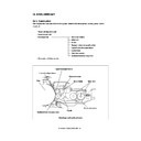
Motor shaft
G10
Idle gear
G48
P25
Idle gear
P25
G25
Copier rear side drive
Mixer-2
G45
Idle gear
G24
Idle gear
G20
Lower and upper
developer sleeves
G17
Mixer-1
G24
G45
Paddle
Drive input gear
G27
Rear paddle gear
G31
Front paddle gear
G18
Developer unit
Rear side
Idle gear
G19
Transport
sleeve
G23
Front side
Idle gear
G20
Idle
gear
Scattered toner
recovery roller
G20
G18
G16
Idle
gear
G30
G16
Developer unit drive
AR-651/810 DEVELOPER UNIT 12 - 6
12. 4. Motor Drive Circuit
12. 4. 1. New toner supply motor
12. 4. 1. New toner supply motor
The new toner supply motor (brush motor) is a motor for supplying toner to the developer unit from the
toner cartridge. It is driven by the motor driver IC38, and its circuit configuration is shown in the
following.
IC56
IC38
TRSM1A-0
TRSM1B-0
New toner supply motor
Gate array
Motor
driver
Signal level for motor circuit
Signal
State
TRSM1A-0 TRSM1B-0
L
L
OFF
Level
H
L
CW (when supplying toner)
L
H
CCW (detecting cartridge installation)
H
H
Brake
AR-651/810 DEVELOPER UNIT 12 - 7
12. 4. 2. Developer motor
5.1V
Phase
comparator
Current
detection
circuit
Rotation
control
Roter
position
detector
Excited
phase
switching
unit
Speed
comparator
Wave
shaping
Control
signal
signal
Difference
Difference
Reference
requency
requency
DEVON
DEVCK
+24VA
FG pulse
W-phase
V-phase
U-phase
A, B, C: Hall element
C
Developer motor
(M13)
(M13)
B
A
(1) The LGC transmits control signals for the developer motor rotation (DEVON: motor rotation com-
mand).
(2) The excitation phase switching unit excites each phase on the developer motor. Developer motor
rotates.
(3) Hall elements A to C are used to detect the rotational position of the motor (rotor).
(4) The excitation phase switching unit switches the excitation for each phase. (By repeating steps (2)
through (4) above, the motor keeps rotating.)
(5) The FG pulse is generated by the rotation of the developer motor.
(6) The phases and velocities of the FG pulse and the reference frequency from the LGC are compared,
and the differences are added. Further to this are added the fluctuations in the power supply voltage
(signal generation).
(7) Changes the switching timing for the excitation phase switching unit to match the signal amount
obtained in step (6).
That is, the FG pulse and reference frequency are controlled to be equal. The developer motor
rotates at a constant speed (locked range state).
(8) When the DEVON signal changes to “H” level, the developer motor stops.
AR-651/810 DEVELOPER UNIT 12 - 8
<Control signals>
(1) DEVCK signal (LGC DEV-MOT: input)
This signal is a reference clock signal for the developer motor to rotate at a fixed speed. The frequency
of the reference clock is 821.2Hz.
When the cycle of the FG pulse deviation from the reference frequency is within +6.25%, this state is
specified as lock range (normal rotation). Also, at this time, the LED “D4” light comes ON.
(2) DEVON signal (LGC DEV-MOT: input)
This signal is the motor ON/OFF control signal. When it becomes “L” level, the motor rotates.
Signal level for motor circuit
Signal
“H” level
“L” level
DEVCK Reference clock (821.2Hz)
DEVON
Motor OFF
Motor ON
Click on the first or last page to see other AR-651 (serv.man15) service manuals if exist.

