Sharp AR-505 (serv.man8) Service Manual ▷ View online
2) Disconnect the connector from the CN9 on the control PWB, and
connect the short connector (OCW4074K526//) instead.
3) Remove the ADF/RADF top cover, and set the DIP switch on the
control PWB to the desired test mode. While pressing the push
switch ON, turn on the power of the machine.
switch ON, turn on the power of the machine.
(With the above operation, the machine enters the test mode.)
4) Turn on the push switch on the control PWB.
(Test operation is started.)
(To switch to another test mode, set the DIP switch on the control
PWB to the desired test mode, and open/close the ADF/RADF paper
feed section cover (microswitch FGOD is turned OFF and ON).
PWB to the desired test mode, and open/close the ADF/RADF paper
feed section cover (microswitch FGOD is turned OFF and ON).
·
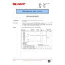
DIP switch 3 meaning
ON
OFF
DIP switch 3
For AB series
For inch series
·
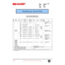
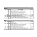
Kinds of test modes and setting of DIP switch
No.
Test mode name
DIP switch
a
Single paper pass mode
All OFF
b
Duplex paper pass mode
1 ON,
the others OFF
the others OFF
c
Single aging mode
1, 3 ON,
2, 4, 5 OFF
2, 4, 5 OFF
d
Duplex aging mode
4 ON,
the others OFF
the others OFF
e
Load check mode
1, 5 ON,
2, 3, 4, OFF
2, 3, 4, OFF
f
EEPROM initializing mode + all
sensors adjustment mode
sensors adjustment mode
3, 5 ON,
1, 2, 4, OFF
1, 2, 4, OFF
g
Resist sensor adjustment mode
4, 5 ON,
1, 2, 3, OFF
1, 2, 3, OFF
h
Timing sensor adjustment mode
1, 4, 5, ON,
2, 3, OFF
2, 3, OFF
i
Paper exit sensor adjustment mode
(AR-RF1 only)
(AR-RF1 only)
3, 4, 5, ON,
1, 2, OFF
1, 2, OFF
a. Single paper pass mode (with paper)
When documents are set on the paper feed tray, the document feed
LED lights up. When the push switch is pressed, all documents on the
paper feed tray are fed.
LED lights up. When the push switch is pressed, all documents on the
paper feed tray are fed.
b. Duplex paper pass mode (with paper)
When documents are set on the paper feed tray, the document feed
LED lights up. When the push switch is pressed, all documents on the
paper feed tray are fed.
LED lights up. When the push switch is pressed, all documents on the
paper feed tray are fed.
c. Single aging mode (without paper)
When the push switch is pressed, aging is started. The operation
timing is made by detection of each document size on the tray.
timing is made by detection of each document size on the tray.
d. Duplex aging mode (without paper)
When the push switch is pressed, aging is started. The operation
timing is made by detection of each document size on the tray.
timing is made by detection of each document size on the tray.
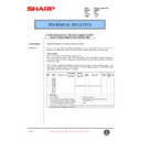
e. Load check mode
Set the DIP switch on the contro PWB as shown below, and open
and close the ADF/ RADF paper feed section cover to enter the load
check mode.
and close the ADF/ RADF paper feed section cover to enter the load
check mode.
(DIP switch)
Every time when the push switch is pressed, the operation is per-
formed in the sequence of 1)
formed in the sequence of 1)
~
21)
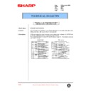
1) Document feed LED ON, Document remain LED ON, Paper
feed solenoid ON
2) Reverse solenoid ON, Paper feed solenoid OFF
3) Document feed LED OFF, Document remain LED OFF, Reverse
solenoid OFF
4) Document feed LED ON, Document remain LED OFF, Paper
feed solenoid ON, Paper feed motor forward rotation 450mm/s
(Preliminary paper feed operation)
(Preliminary paper feed operation)
5) Document feed LED OFF, Document remain LED OFF, Paper
feed solenoid OFF, Paper feed motor OFF
6) Document feed LED ON, Document remain LED ON, Paper
feed motor reverse rotation 450mm/2 (2-step advanced feed)
7) Document feed LED OFF, Document remain LED OFF, Paper
feed motor OFF
8) Document feed LED ON, Document remain LED ON, Paper
feed motor reverse rotation 850mm/s (Paper feed operation)
9) Document feed LED OFF, Document remain LED OFF, Paper
feed motor OFF
10) Document feed LED ON, Document remain LED ON, Transport
motor forward rotation 867mm/s
11) Document feed LED OFF, Document remain LED OFF, Trans-
port motor OFF
12) Document feed LED ON, Document remain LED ON, Transport
motor reverse rotation 867mm/s
13) Document feed LED OFF, Document remain LED OFF, Trans-
port motor OFF
14) Document feed LED ON, Document remain LED ON, Reverse
motor forward rotation 867mm/s (reverse operatoin)
15) Document feed LED OFF, Document remain LED OFF, Reverse
motor OFF
16) Document feed LED ON, Document remain LED ON, Reverse
motor forward rotation 867mm/s (Pulling/paper exit operation)
1)
2)
OFF
ON
SW
No.1
2
3
4
5
AR-505
6 – 28
8/6/1999
17) Reverse motor speed reduction 867
®
297mm/s (Paper exit
speed reduction)
18) Document feed LED OFF, Document remain LED OFF, Reverse
motor OFF
19) Document feed LED ON, Document remain LED ON, Reverse
motor forward rotation 867mm/s (Paper exit operation)
20) Reverse motor speed reduction 867
®
297mm/s (Paper exit
speed reduction)
21) Document feed LED OFF, Document remain LED OFF, Reverse
motor OFF
Kind of JAM, error
LED display
Paper feed motor lock error
REMOVE ORIGINAL LED blinks at
the cycle of 2000msec.
the cycle of 2000msec.
Return to 1).
f. EEPROM initializing + all sensors adjustment mode
When the DIP switch is set (3, 5 to ON, 1, 2, 4 to OFF) the push
switch is pressed, the EEPROM is initialized. At that time, the LED
blinks at the cycle of 100msec.
switch is pressed, the EEPROM is initialized. At that time, the LED
blinks at the cycle of 100msec.
After completion of EEPROM initializing, the LED turns ON. In case of
an error in the EEPROM initializing, the LED blinks at the cycle of
2000msec.
an error in the EEPROM initializing, the LED blinks at the cycle of
2000msec.
Then all sensors adjustment is started. At that time, the document
remain LED blinks at the cycle of 100msec. After completion of all
sensors adjustment, the document remain LED turns ON. In case of
an. Error in the all sensors adjustment, the document remain LED
blinks at the cycle of 2000msec.
remain LED blinks at the cycle of 100msec. After completion of all
sensors adjustment, the document remain LED turns ON. In case of
an. Error in the all sensors adjustment, the document remain LED
blinks at the cycle of 2000msec.
*
Only when the EEPROM is successfully completed, the all sensors
adjustment is performed.
adjustment is performed.
Kinds of JAM, error
LED display
EEPROM initializing error
Ready LED blinks at the cycle of
2000msec.
2000msec.
All sensors adjustment error Document remain LED blinks at the
cycle of 2000msec
g. Resist sensor adjustment mode
Set the DIP switch (4, 5 to ON, 1, 2, 3 to OFF) and press the push
switch. Each sensor adjustment is performed. At that time, the LED
blinks at the cycle of 100msec.
switch. Each sensor adjustment is performed. At that time, the LED
blinks at the cycle of 100msec.
After completion of the sensor adjustment, the LED turns ON. In case
of an error in the sensor adjustment, the LED blinks at the cycle of
100msec.
of an error in the sensor adjustment, the LED blinks at the cycle of
100msec.
Kinds of JAM, error
LED display
Sensor adjustment
upper limit error
upper limit error
Document remain LED turns OFF.
Ready LED blinks at the cycle of 100msec.
Ready LED blinks at the cycle of 100msec.
Sensor adjustment
lower limit error
lower limit error
Document remain LED blinks at the cycle of
100msec.
Ready LED turns OFF
100msec.
Ready LED turns OFF
*
This mode can be adjusted with SIM 53-2.
h. Timing sensor adjustment mode
Set the DIP switch (1, 4, 5 to ON, 2, 3 to OFF) and press the push
switch. Each sensor adjustment is performed. At that time, the LED
blinks at the cycle of 100msec.
switch. Each sensor adjustment is performed. At that time, the LED
blinks at the cycle of 100msec.
After completion of the sensor adjustment, the LED turns ON. In case
of an error in the sensor adjustment, the LED blinks at the cycle of
100msec.
of an error in the sensor adjustment, the LED blinks at the cycle of
100msec.
Kinds of JAM, error
LED display
Sensor adjustment
upper limit error
upper limit error
Document remain LED turns OFF.
Ready LED blinks at the cycle of 100msec.
Ready LED blinks at the cycle of 100msec.
Sensor adjustment
lower limit error
lower limit error
Document remain LED blinks at the cycle of
100msec.
Ready LED turns OFF
100msec.
Ready LED turns OFF
*
This mode can be adjusted with SIM 53-2.
i. Paper exit sensor adjustment mode
Set the DIP switch (3, 4, 5 to ON, 1, 2 to OFF) and press the push
switch. Each sensor adjustment is performed. At that time, the LED
blinks at the cycle of 100msec.
switch. Each sensor adjustment is performed. At that time, the LED
blinks at the cycle of 100msec.
After completion of the sensor adjustment, the LED turns ON. In case
of an error in the sensor adjustment, the LED blinks at the cycle of
100msec.
of an error in the sensor adjustment, the LED blinks at the cycle of
100msec.
Kinds of JAM, error
LED display
Sensor adjustment
upper limit error
upper limit error
Document remain LED turns OFF.
Ready LED blinks at the cycle of 100msec.
Ready LED blinks at the cycle of 100msec.
Sensor adjustment
lower limit error
lower limit error
Document remain LED blinks at the cycle of
100msec.
Ready LED turns OFF
100msec.
Ready LED turns OFF
*
This mode can be adjusted with SIM 53-2.
(4) Kinds of error (RADF single mode only)
Kinds of JAM, error
LED display
Not-reaching/remaining JAM in
the paper feed section
the paper feed section
Document remain LED blinks at
the cycle of 1000msec.
the cycle of 1000msec.
Not-reaching/remaining JAM in
the paper exit section
the paper exit section
Ready LED blinks at the cycle
of 1000msec.
of 1000msec.
Paper feed motor lock error
Document remain LED blinks at
the cycle of 2000msec.
the cycle of 2000msec.
Resist/timing sensor
adjustment error (when power
is supplied)
adjustment error (when power
is supplied)
Document remain LED blinks at
the cycle of 100msec.
the cycle of 100msec.
Paper exit sensor adjustment
error (when power is supplied)
error (when power is supplied)
Ready LED blinks at the cycle
of 100msec.
of 100msec.
A JAM/motor lock error can be canceled by opening/closing the ADF
after jam recovery process or by applying the power again.
after jam recovery process or by applying the power again.
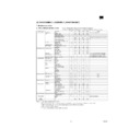
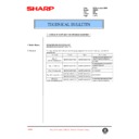
K. RSPF
There are following items of adjustments by the simulations of the
machine.
machine.
Name
Adjustment items
Adjustment
value
(Key
operation on
the machine)
Note
Lead edge
position
adjustment
position
adjustment
The lead edge and the
image lead edge are
adjusted in the range of
+5mm to +5mm.
(Front and back surface
of a document)
image lead edge are
adjusted in the range of
+5mm to +5mm.
(Front and back surface
of a document)
0
~
100
SIM 50-1/2
SIM 50-6/7
Default: 50
SIM 50-6/7
Default: 50
Magnification
ratio
adjustment
ratio
adjustment
The magnification ration
is corrected. (–4.9% to
+4.9%)(Front and back
surface of a document)
is corrected. (–4.9% to
+4.9%)(Front and back
surface of a document)
1
~
99
SIM 48-1
Default: 50
Default: 50
Resist
quantity
adjustment
quantity
adjustment
No. 1 resist (front surface
of document) loop
quantity adjustment
(0.1mm
of document) loop
quantity adjustment
(0.1mm
~
9.9mm)
1
~
99
SIM 51-2
Default: 50
Default: 50
No. 2 resist (front surface
of document) loop
quantity adjustment
(0.1mm
of document) loop
quantity adjustment
(0.1mm
~
6.9mm)
31
~
99
SIM 51-2
Default: 50
Default: 50
Image loss
adjustment
adjustment
The output timing of data
enable signal (DEN) is
adjusted and data write
from the image lead edge
to the set quantity is cut.
(0
enable signal (DEN) is
adjusted and data write
from the image lead edge
to the set quantity is cut.
(0
~
10mm)
0
~
100
SIM 50-1/2
SIM 50-6/7
Default: 50
SIM 50-6/7
Default: 50
Center shift
adjustment
adjustment
SIM 50-12
Reflection
type sensor
adjustment
type sensor
adjustment
Automatic initialization of
the post-separation
sensor, the read sensor,
and the SB sensor is
performed.
the post-separation
sensor, the read sensor,
and the SB sensor is
performed.
SIM 53-2
AR-505
8/6/1999
6 – 29
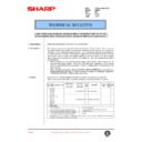
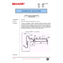
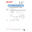
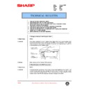
Image distortion adjustment procedure
Adjustment of hinge base dimension T of hinge ass’y R
(1) Loosen the RSPF fixing screw.
(2) Loosen the nut and turn the distortion adjustment screw to adjust
dimension T.
(3) Tighten two SPF fixing screws to fix the hinge base.
(4) Tighten the nut with the distortion adjustment screw fixed.
(Adjustment 1) Turn the distortion adjustment screw in direction of A.
— Dimension T is increased.
(Adjustment 2) Turn the distortion adjustment screw in direction of B.
— Dimension T is decreased.
(Adjustment procedure)
1) Perform Adjustment 1 to adjust the distortion in X section.
1) Perform Adjustment 1 to adjust the distortion in Y section.
Back surface resist adjustment
Back surface resist adjustment by the SB resist adjustment plate
(1)
Loosen the fixing scrw.
(2)
If the copied image is as shown in 1, shift and adjust the adjust-
ment plate in the direction of A.
ment plate in the direction of A.
If the copied image is as shown in 2, shift and adjust the adjust-
ment plate in the direction of B.
ment plate in the direction of B.
(Set document)
(Copy)
Copy
1
Copy
2
RSPF fixing screw
Hinge ass'y
Hinge ass'y L
PPC body
R-SPF
Slide the RSPF according to the adjustment.
A
B
Arrow view Z
T
Hinge base
adjustment scale line
adjustment scale line
RSPF fixing screw
Hinge ass'y R
Hinge base
Distortion
adjustment screw
Nut
Z
SPF adjustment direction by rotation
of the distortion adjustment screw
Front surface of copy
Document feed direction
1
X
X
Front surface of copy
Y
Y
2
A
B
SB resist
adjustment plate
Fixing screw
Float side plate F
B
Front surface of document
B
B
AR-505
6 – 30
8/6/1999
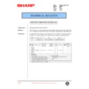
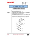
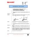
Skew adjustment
Skew adjustment by the upper guide and the lower guide
(1) Loosen four fixing screws.
(2) If the copied image is as shown in
1
, shift and adjust the adjust-
ment plate in the direction of A. If the copied image is as shown in
2
, shift and adjust the adjustment plate in the direction of B.
(Set document)
(Copy)
Copy 1
Copy 2
Fixing screws
F-side plate adjustment scale line
B
A
A
Front surface
of document
A
A
AR-505
8/6/1999
6 – 31

