Sharp AR-155 (serv.man11) Service Manual ▷ View online
SW
No.
No.
Bit
No.
ITEM
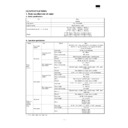
Soft SW setting and function
Factory Setting
28
1
2
3
4
2
3
4
Used to set the silent detection time in the answering and
recording mode.
The set range is OFF and 1 to 10sec.
recording mode.
The set range is OFF and 1 to 10sec.
Time = 8
× Bit1 + 4 × Bit2 + 2 × Bit3 + 1 × Bit4 sec
Effective : 0(= OFF), 1 –10
0
1
0
1
1
0
1
5
Answering and recording mode
auto reception select
auto reception select
Used to set whether FAX reception is started or not after 6
call rings if the answering function does not work for some
reasons in the answering and recording mode.
call rings if the answering function does not work for some
reasons in the answering and recording mode.
0
6
Annoying FAX prevention function
Used to set ON/OFF of the annoying FAX prevention
function.
function.
0
7
Polling function
Used to set whether one-touch key “20” is used as the
polling key or not.
polling key or not.
0
8
Reserved
0
29
1
2
2
Record paper size (Main Tray)
Used to set the record paper size in the main tray.
LTR
3
Reserved
0
29
4
5
5
Record paper size (2nd Tray)
Used to set the record paper size in the 2nd tray.
A4 for AB series
LTR for Inch series
LTR
6
Reserved
0
7
Reserved
0
8
Index print
Used to set whether marking is made to the lead edge of
paper or not to identify the job when printing the received
data.
paper or not to identify the job when printing the received
data.
1
30
1
Reserved
0
2
Reserved
0
3
Reserved
0
4
Reserved
0
5
Reserved
0
6
Reserved
0
7
Reserved
0
8
Reserved
0
1 : ON
0 : OFF
1 : ON
0 : OFF
1 : ON
0 : OFF
Bit No.
Letter
Legal
A4
Other
1
0
0
1
1
2
0
1
0
1
Bit No.
Letter
Legal
A4
Other
4
0
0
1
1
5
0
1
0
1
1 : ON
0 : OFF
AR-F151
9 – 28
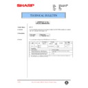
5. TROUBLE CODES
A. Trouble codes list
Main
code
code
Sub
code
Trouble content
Detail of trouble
E7
01
Duplex model memory setup error,
memory not-detected error
memory not-detected error
The memory is not set properly or the memory capacity is not set to the duplex setup
(6M).
Cancel method: Set SIM 26-39 code number to 2.
(6M).
Cancel method: Set SIM 26-39 code number to 2.
E7
03
HSYNC not detected.
LSU (laser diode, reception element, APC circuit) trouble
LSU drive circuit (ASIC) trouble
LSU drive circuit (ASIC) trouble
E7
04
CCD white level trouble
CCD drive circuit (CCD PWB, ASIC harness) trouble
Copy lamp lighting trouble (Copy lamp, invertor PWB)
Copy lamp lighting trouble (Copy lamp, invertor PWB)
E7
05
CCD black level trouble
CCD drive circuit (CCD PWB, ASIC, harness) trouble
E7
12
Shading trouble (White correction)
Dirt on white plate for scanning white level
E7
14
ASIC connection trouble
Improper connection between CPU and ASIC (pattern cut, improper connection of lead
pin)
pin)
E7
15
Copy lamp disconnection trouble
Copy lamp or copy lamp drive circuit (invertor PWB) trouble Copy lamp disconnection
L1
00
Feeding is not completed within
the specified time after starting
feeding.
the specified time after starting
feeding.
When the mirror base is returned for the specified time (6 sec) in mirror initializing
after turning on the power, the mirror home position sensor (MHPS) does not turn
OFF. Or when the mirror base is fed for the specified time (about 6 sec) after start of
copy return, the mirror home position sensor (MHPS) does not turn OFF.
after turning on the power, the mirror home position sensor (MHPS) does not turn
OFF. Or when the mirror base is fed for the specified time (about 6 sec) after start of
copy return, the mirror home position sensor (MHPS) does not turn OFF.
L3
00
Return is not completed within the
specified time.
specified time.
When the mirror base is returned for the specified time (6 sec) in mirror initializing
after turning on the power, the mirror home position sensor (MHPS) does not turn
ON.Or when the mirror base is returned for the specified time (about 6 sec) after start
of copy return, the mirror home position sensor (MHPS) does not turn ON.
after turning on the power, the mirror home position sensor (MHPS) does not turn
ON.Or when the mirror base is returned for the specified time (about 6 sec) after start
of copy return, the mirror home position sensor (MHPS) does not turn ON.
L4
01
Main motor lock
When the main motor encoder pulse is not detected for 100msec.
L6
10
Polygon motor lock
The lock signal (specified rpm signal) does not return within a certain time (about
20sec) from starting the polygon motor rotation
20sec) from starting the polygon motor rotation
H2
00
Thermistor open detection
The fusing thermistor is open.
H3
00
Heat roller abnormally high
temperature
temperature
The fusing temperature rises above 240˚C.
H4
00
Heat roller abnormally low
temperature
temperature
The fusing temperature does not reach 185˚C within 27 sec of turning on the power,
or the fusing temperature keeps at 140˚C.
or the fusing temperature keeps at 140˚C.
U2
01
Counter sum check error
When the counter check sum value stored in the EEPROM is abnormal.
U2
04
EEPROM serial communication
error
error
When a communication trouble occurs with the EEPROM.
F6
80
Communication trouble with FAX
PWB (Protocol)
PWB (Protocol)
Error in data reception from the FAX board to the MCU.
Occurs when the message header of the message format is other than F.
Cancel method: Turn OFF/ON the power.
Occurs when the message header of the message format is other than F.
Cancel method: Turn OFF/ON the power.
F6
81
Communication trouble with FAX
PWB (Parity)
PWB (Parity)
Error in data reception from the FAX board to the MCU.
Occurs when the odd number parity set with SMR (serial mode register) differs from
the reception data.
Cancel method: Turn OFF/ON the power.
Occurs when the odd number parity set with SMR (serial mode register) differs from
the reception data.
Cancel method: Turn OFF/ON the power.
F6
82
Communication trouble with FAX
PWB (Overrun)
PWB (Overrun)
Error in data reception from the FAX board to the MCU
Occurs when the next data reception is completed with RDRF (Receive Data Register
Full) flag of SS (Reserial status register) set to 1.
Cancel method: Turn OFF/ON the power.
Occurs when the next data reception is completed with RDRF (Receive Data Register
Full) flag of SS (Reserial status register) set to 1.
Cancel method: Turn OFF/ON the power.
F6
84
Communication trouble with FAX
PWB (Framing)
PWB (Framing)
Error in data reception from the FAX board to the MCU.
Occurs when the stop bit is 0. (The stop bit must be 1.)
Cancel method: Turn OFF/ON the power.
Occurs when the stop bit is 0. (The stop bit must be 1.)
Cancel method: Turn OFF/ON the power.
F6
88
Communication trouble with FAX
PWB (Time-out)
PWB (Time-out)
Occurs when time is out without response in data communication between the FAX
board and the MCU.
Cancel method: Turn OFF/ON the power.
board and the MCU.
Cancel method: Turn OFF/ON the power.
F6
10
FAX PWB trouble
Communication trouble between the MCU and the FAX board or between the FAX
board and the FAX panel
Cancel method: Turn OFF/ON the power. Check connections.
board and the FAX panel
Cancel method: Turn OFF/ON the power. Check connections.
AR-F151
9 – 29
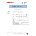
[10] ERROR MESSAGE AND TROUBLESHOOTING
1. Error message
Error check can be also made on the LCD of the operation.
Display Error content Process
SERVICE CALL (1) PCU ROM error Check the IC304 peripheral circuit on the PS/PCU PWB
SERVICE CALL (2) PCU RAM error Check the IC304 peripheral circuit on the PS/PCU PWB
SERVICE CALL (3) Serial commnication error Check the IC304 peripheral circuit on the PS/PCU PWB
Check the PMD/APCSTT/PMCLK/SYNC signals on the PS/PCU PWB.
SERVICE CALL (5) High Temperature Error Check the thermistor peripheral circuit and the heater lamp control circuit on the PS/PCU
PWB.
SERVICE CALL (6) Low Temperature Error Check the AC line and the HLON signal on the PS/PCU PWB.
Check the temperature fuse.
SERVICE CALL (7) Thermistor Open Check the thermister peripheral circuit on the PS/PCU PWB.
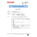
FAX communication error code
Transmission error Reception error
E-0 Able to recognize handshake signal, but it has errors.
(The bit stream after flag has some error)
E-0 Able to recognize handshake signal, but it has errors.
(The bit stream after flag has some error)
E-1 Cannot recognize the handshake signal from the receiver
side. (
*
NFS/DIS)
E-1 Line disconnected during reception. (
*
NSS/DCS)
E-2 Line disconnected during transmission. (
*
CFR) E-2 Cannot recognize the handshake signal from the transmitter
side. (
*
NSC/DTC)
E-3 Line disconnected after modem speed fall back. (
*
FTT) E-3 Cannot recognize the last handshake signal from the
transmitter side. (
*
EOP)
E-4 Line disconnected during multi-page transmission. (
*
MCF) E-4 Cannot recognize the handshake signal for next page from
the transmitter side in the case of mode change. (
*
EOM)
Not defined E-5 Cannot recognize the handshake signal for next page from
tranmitter side. (
*
MPS)
E-6 Cannot recognize the handshake signal for next page at
receiver side. (
*
RTN/RTP)
Not defined
E-7 "diconnect signal" is received at transmitter side. (
**
DCN) E-7 "disconnect signal" is received at receiver side. (
**
DCN)
E-8 Error was not corrected after the predetermined number of
retries because of an error in a part of a page. (
*
PPR)
E-8 Error occurred upon completion of reception of all pages.
(
*
PPS-EOP)
Not defined E-9 Error occurred when mode was changed or
transmission/reception switching was perfromed.
(
(
*
PPS-EOM)
Not defined E-10 Error occurred during partial page or physical page
reception. (
*
PPS-MPS/NULL)
E-11 Not defined E-11 Not defined
E-12 Error occurred just after fall-back (
*
CTR) E-12 Error occurred during or just after fallback. (
*
CTC)
E-13 Error occurred after a response to a retransmission end
command was received. (
*
ERR)
E-13 Error occurred after retransmission end command was
received. (
*
EOR)
Remark (
*
signal): If some error happen after this signal is received, the controller reports this error.
(
**
DCN): If the unexpected "DCN" signal is received, the controller reports this error.
Action: Stop the fax transmission/reception.
Recover: Press STOP key
9/7/1999 10 – 1

