Sharp AL-800 (serv.man3) Service Manual ▷ View online
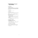
G. Electrical section
(1) Block diagram
a. Major sections operations and functions
MCU (PCU) PWB
The CPU controls the engine, and the ASIC performs image process.
Image data (analog signals) from the scanner (reading) section are
converted into digital signals by the A/D convertor and image process
(area separation, filter process, gamma correction, resolution conver-
sion, zooming) is performed by the ASIC and the line memory
(SRAM). The processed data are outputted to the scanner (writing)
section.
During printing, the dot image data from the ICU PWB are received
and outputted to the scanner (writing) section straightly. The CPU
controls the machine operations according to the key operation sig-
nals from the operation PWB. The loads (motor, lamp. solenoid, high
voltage power PWB, etc.) are controlled according to the sensors and
detectors signals. At the same time, the machine status data are
outputted to the operation section and the ICU PWB.
CCD PWB
CPU
H8S
H8S
DRAM
ASIC
I/F
A/D
EEPROM
RAM
ROM
SRAM
32kX8
32kX8
SRAM
32kX8
32kX8
Power SW
DRAM
16Mbit
16Mbit
DRAM
16Mbit
16Mbit
DRAM
16Mbit
MCU (PCU) PWB
Image process ASIC
CCD control
Data select
Motor driver
ICU PWB
Paper in sensor
High voltage
PWB
Driver
Motor driver
High voltage unit
Main charger roller
Drum
OPC cartridge
LSU unit
Laser
Pickup solenoid
Main motor
Transfer roller
Polygon motor
CCD
Amplifier
Scanner motor
FAN motor
Home position sensor
Paper size sensor
Toner sensor
Invertor
Scanner
lamp
Image
process
Heat roller
Thermistor
Heater lamp
Power PWB unit
Developer cartridge
Doctor
Earth sheet
Developing
roller
Control
electrode
Paper exit
sensor
Laser beam
sensor
Operation panel PWB
Key switch
Display lamp
Temperature
fuse
Temperature
fuse
1 – 28
ICU PWB
Print data from the host (PC) are developed by the ASIC and the line
memory (DRAM) to converted into full dot image data, which are then
outputted to the data select section in the MCU PWB. The machine
status data from the MCU PWB are outputted tot he host (PC). In
addition. the ASIC controls the parallel I/F.
memory (DRAM) to converted into full dot image data, which are then
outputted to the data select section in the MCU PWB. The machine
status data from the MCU PWB are outputted tot he host (PC). In
addition. the ASIC controls the parallel I/F.
Operation PWB
Status data from the MCU PWB are converted into the lamp and
lamp display by the display controller. The key operations are con-
verted into key data signals and outputted to the MCU (PCU) PWB.
lamp display by the display controller. The key operations are con-
verted into key data signals and outputted to the MCU (PCU) PWB.
High voltage power PWB
This PWB supplies the high voltage used in the image process sec-
tion. (Main charger, developing bias, transfer charger) It also includes
the driver for the main motor. The power output is controlled by the
control signals from the MCU (PCU) PWB.
tion. (Main charger, developing bias, transfer charger) It also includes
the driver for the main motor. The power output is controlled by the
control signals from the MCU (PCU) PWB.
Copy lamp control PWB
The copy lamp light quantity is controlled so that the necessary quan-
tity of light is provided even when conditions of the scanner (reading)
section are changed.
tity of light is provided even when conditions of the scanner (reading)
section are changed.
The copy lamp drive voltage is controlled by the output level of the
light quantity sensor in the scanner (reading) section. Control is made
with the control signals from the MCU (PCU) PWB.
light quantity sensor in the scanner (reading) section. Control is made
with the control signals from the MCU (PCU) PWB.
Power PWB
The power PWB outputs DC power voltages (+24V, +5V, +3.3V,
+12V) and drives the heater lamp.
+12V) and drives the heater lamp.
CN11
CN12
CN14
CN10
CN6
CN5
CN4
CN1
CN2
CN7
CN13
CN9
CN8
IC5
CPU
H8S/2350
IC8
ASIC
HG73C025FD
IC13
IC112
MRMT0~3
MHPS_IN
CLCNT
PSIZE_IN
TS_IN
VFMOUT
RTH_IN
PSIZE_IN
CCDOUT
f1,f2,
SH-,RS,
SP,CP
PMCLK
PMD-
PEMP_IN
VDATA
DSRDY-,RESERR-
DPAGE-,VIDEO
VSYNC-,PRSTT
RESET,DREADY-
DCRDY-,ERROR
SCLK,SYNC
PIN_IN-
FW
MEN-,MMT0,1
MCON,HL,TC/BIASON
PUS,PR,PWMSIN
OPPSW
OPKIN1,2
OPCLK,OPLATCH
OPDATA,SELIN1,2,3
MCU PWB BLOCK DIAGRAM
SCANNER
MOTOR
CCD PWB
INVERTOR
PWB
THERMISTOR
OPERATION PANEL
FAN MOTOR
HIGH VOLTAGE PWB
TONER
SENSOR
LSU PWB
LASER
POLYGON
MOTOR
ICU PWB
PAPER
EXIT
SENSOR
HOME
POSITION
SENSOR
PAPER
SIZE
SENSOR
PAPER
EMPTY
SENSOR
CN202
CN201
IC201
DRAM
CN203
MCU
PWB
PWB
ICU PWB
IC202
GATE ARRAY
TO PC
TO PC
OPERATION PWB BLOCK DIAGRAM
CN-901
KEY SWITCH
LAMP, VALUE DISPLAY LED
DISPLAY CONTROLLER (DRIVER)
IC901
DECODER
IC902
MCU PWB
1 – 29
q
1998 BY SHARP CORPORATION
Printed in Japan.
SHARP CORPORATION
Printing Reprographic Systems Group
Quality & Reliability Control Center
Yamatokoriyama, Nara 639-1186, Japan
Printing Reprographic Systems Group
Quality & Reliability Control Center
Yamatokoriyama, Nara 639-1186, Japan
1998 October Printed in Japan
S

