Sharp AL-1566 (serv.man11) Service Manual ▷ View online
AL-1556/1566 DISASSEMBLY AND ASSEMBLY 8 - 13
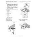
6. Manual paper feed section
A. List
B. Disassembly procedure
Multi unit
1) Remove the screw and remove the multi upper cover.
2) Remove the screw and remove the side door detection unit.
3) Remove three screws and remove the multi paper feed upper
frame.
4) Remove two screws and remove the multi feed bracket unit from
the multi paper feed upper frame.
No.
Part name Ref.
1
Manual transport roller
2
Cassette detection switch
3
PPD1 sensor PWB
4
Side door detection unit
2)
1)
1)
2)
Back
Wire treatment
1)
2)
1)
2)
2)
1)
1)
AL-1556/1566 DISASSEMBLY AND ASSEMBLY 8 - 14
5) Remove three E-rings and remove the manual paper feed roller
B9.
6) Remove the pick-up roller.
7) Cut the binding band and remove the multi paper feed solenoid.
C. Assembly procedure
For assembly, reverse the disassembly procedure.
D. Pressure plate holder attachment
1) Attach the pressure plate holder so that the resin section is not
covered with the seal M1-N.
2)
1)
1)
1)
3)
L
O C
K
T
O
K
2)
1)
1)
2)
3)
Multi paper feed
solenoid
solenoid
Pressure plate
holder
holder
Seal M1-N
Attachment
reference
reference
Attachment
reference
reference
AL-1556/1566 DISASSEMBLY AND ASSEMBLY 8 - 15
7. Rear frame section
A. List
B. Disassembly procedure
1) Remove the rear cabinet.
2) Remove the connector, the flat cable, and the grounding wire.
3) Remove three screws, and remove the FAX PWB.
4) Disconnect the connector.
5) Remove two screws, and remove the scanner motor.
6) Remove two screws and one harness, and remove the main
motor.
7) Remove two screws and one connector, and remove the exhaust
fan motor.
Note: Be careful of the installing directions of the fan.
Attach it so that the blowing direction faces outside.
8) Disconnect the connector.
9) Remove the two screws, and remove the NIC PWB.
10) Disconnect the connector.
11) Remove the two screws, and remove the NIC PWB unit.
No.
Part name Ref.
1
FAX PWB
2
Mirror motor
3
Main motor
4
Exhaust fan motor
5
NIC PWB
6
Main PWB
2)
2)
1)
1)
3)
2)
2)
1)
3)
2)
1)
2)
3)
1)
2)
3)
Blowing direction
2)
2)
3)
1)
2)
2)
3)
3)
1)
AL-1556/1566 DISASSEMBLY AND ASSEMBLY 8 - 16
12) Disconnect the connectors.
13) Remove the five screws, and remove the MCU PWB.
C. Assembly procedure
For assembly, reverse the disassembly procedure.
8. Power section
A. List
B. Disassembly procedure
1) Disconnect each connector.
2) Remove the screw, and remove the earth line.
3) Remove two screws, and remove the power PWB unit.
C. Assembly procedure
For assembly, reverse the disassembly procedure.
9. Duplex motor section (RSPF model only)
A. List
B. Disassembly procedure
1) Remove the rear cabinet.
2) Remove two screws.
3) Remove the Duplex motor cover.
4) Remove the Duplex motor.
Note: When reassembling, be sure to engage the Duplex motor gear
with the belt on the main body side.
C. Assembly procedure
For assembly, reverse the disassembly procedure.
10. Reverse roller section (RSPF model
only)
A. List
B. Disassembly procedure
1) Remove four screws
2) Remove the spring, and the earth wire
3) Remove the reverse unit.
No.
Part name Ref.
1
Power PWB
1)
1)
1)
2)
2)
3)
2)
2)
2)
1)
1)
1)
1)
2)
3)
4)
4)
5)
1)
No.
Part name Ref.
1
Duplex motor
No.
Part name Ref.
1
Reverse roller
1
2
3
1
1
2
3
Click on the first or last page to see other AL-1566 (serv.man11) service manuals if exist.

