Sharp LL-T2010W (serv.man15) Service Manual ▷ View online
LL-T2010W
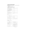
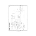
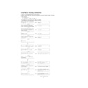
TROUBLE SHOOTING
4 – 5
(No)
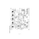
Are the adjustment contents saved after
completion of the display adjustment?
completion of the display adjustment?
Check the IC13, and IC15 peripheral
circuits.
circuits.
(Yes)
(No)
Can inputs be switched normally?
(Yes)
There is no abnormality.
Check the IC1, IC2, IC3, and IC4
peripheral circuits.
peripheral circuits.
Continued from
4
(No)
Is the positive side (no connection of part)
of C145 at H level (DC+5V)?
of C145 at H level (DC+5V)?
Check the RESET circuit in the
peripheral of IC16.
peripheral of IC16.
(Yes)
(No)
Is the output of Q7 (connected with R161)
at L level (DC+0V)?
at L level (DC+0V)?
(Yes)
Check the Q7 peripheral circuits.
(No)
Are IC15 44PIN and 33PIN at DC+5V?
(Yes)
Check the abnormal line.
(No)
Are the waveforms of RN30, R169, and
R171 outputted?
R171 outputted?
Check IC8.
(Yes)
Check RN30, R169, R171 (IC5 and IC8
control line).
control line).
5
(No)
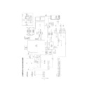
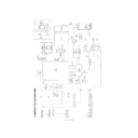
Is the display normal with analog inputs?
First, check with analog inputs.
(Yes)
(No)
Is DC+5V applied to CN2-14PIN?
(Yes)
Check CN2 and the signal source.
(Yes)
Are the signal levels of CN2-1PIN, 2PIN,
9PIN, 10PIN, 17PIN, 18PIN 23PIN, and
24PIN changed?
9PIN, 10PIN, 17PIN, 18PIN 23PIN, and
24PIN changed?
(No)
IC8 abnormality
(No)
When resolution is changed, are the
waveforms of IC7-1PIN and 2PIN
changed normally?
waveforms of IC7-1PIN and 2PIN
changed normally?
Check IC7 and IC8.
(Yes)
Check the IC7 peripheral circuits.
PC display does not work. (Digital DVI)
LL-T2010W
TROUBLE SHOOTING
4 – 6
(No)
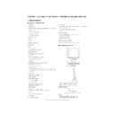
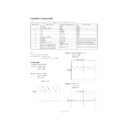
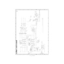
Is the unit connected to the analog input
CN1?
CN1?
Connect the firmware upgrade jig to the
analog input CN1.
analog input CN1.
(Yes)
(No)
Is a jig connected to CN3?
Connect the jig to CN3.
(Yes)
(No)
Are CN3-1PIN, 2PIN, and 3PIN at the
same potential?
same potential?
Check CN3 and the jig connected to
CN3.
CN3.
(Yes)
(No)
Are CN3-1PIN, 2PIN, and 3PIN at
DC+12V?
DC+12V?
Check R173 and the 12V line from the
DCJACK PWB.
DCJACK PWB.
(Yes)
(No)
Is the output of Q18 at L (DC0V)?
Check the Q18 peripheral circuits.
(Yes)
(No)
Is WRPG_SEL at DC+5V?
Check the R179~R181 peripheral
circuits.
circuits.
(Yes)
(No)
Are IC6-1PIN and 13PIN changed
properly?
properly?
(Yes)
Check IC15-31PIN, 32PIN, 33PIN, 35PIN,
and 44PIN. (IF there is no abnormality,
IC15 is defective.)
and 44PIN. (IF there is no abnormality,
IC15 is defective.)
Check the IC6 peripheral circuits.
Firmware upgrade cannot be made.
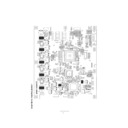
Display

