Sharp LL-T2010W (serv.man13) Service Manual ▷ View online
LL-T2010W
CONNECTION, ADJUSTMENT, OPERATION, AND FUNCTIONS
2 – 1
CHAPTER 2. CONNECTION, ADJUSTMENT, OPERATION, AND FUNCTIONS
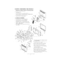
1. CONNECTING THE MONITOR AND TURNING THE MONITOR ON AND OFF
■
■
■
■
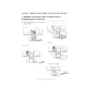
CONNECTING THE MONITOR TO A POWER SOURCE
Use only the AC adapter supplied.
Note: Do not overly bend the cable or add extension cords as this
could lead to malfunction.
1.
Remove the stand cover.
2.
Remove the cover.
3. Connect the AC adapter to the monitor’s power terminal.
4. Replace cover.
5. Connect power cord to AC adapter.
(Rear View)
Stand cover
Lift one side
Cover
Place cord
on hook
AC adapter
Run cord
through hole.
Power terminal
Cover
Power cord
LL-T2010W
CONNECTION, ADJUSTMENT, OPERATION, AND FUNCTIONS
2 – 2
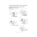
Fitting the AC adapter inside the stand
6.
Replace stand cover.
7.
Place power plug into AC outlet.
■
■
■
■
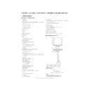
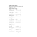
CONNECTING THE MONITOR TO A COMPUTER
(PC ETC.)
Connect using this device’s analog signal cable
Connect this device’s analog signal cable to the computer (PC etc.).
When connecting, ensure that both the monitor and computer are
switched off.
Be careful not to overly bend the cable or add extension cords as this
could lead to malfunction.
could lead to malfunction.
If connecting to a D-sub 15 pin 2 row Apple Power Macintosh, attach a
Macintosh conversion adapter (commercially available) to the analog
signal cable.
signal cable.
Note: If connecting to the Sun Ultra series, a conversion adapter (com-
mercially available) may be required.
Wind the cord
Place adapter
inside stand
cavity.
inside stand
cavity.
2
Stand cvero
1
1
Analog signal cable
Firmly insert the analog RGB output terminal
(mini D-sub 15 pin with 3 rows) then tighten
the screws each side.
(mini D-sub 15 pin with 3 rows) then tighten
the screws each side.
Macintosh conversion adapter
Analog signal cable
After connecting the adapter, tighten the
screws on each side to fix into place.
screws on each side to fix into place.
LL-T2010W
CONNECTION, ADJUSTMENT, OPERATION, AND FUNCTIONS
2 – 3
Connect using a display cable (to be purchased separately)
• Using a display cable (to be purchased separately), it can be con-
nected to the computer’s (PC etc.) digital RGB output terminal or ana-
log RGB output terminal.
.
To connect to a digital RGB output terminal: Digital signal cable
(model name: NL-C01E)
.
To connect to an analog RGB output terminal: Analog signal cable
(model name: NL-C02E)
(model name: NL-C02E)
• For a digital signal input: It can be connected to a computer with a
DVI-compatible output terminal (DVI-D24 pin or DVI-I29 pin) and
which has UXGA output ability. Depending on the computer to be
connected, correct display may or may not be possible.
connected, correct display may or may not be possible.
• Be careful not to overly bend the cable or add extension cords as this
could lead to malfunction.
1.
Remove the cover.
2.
Connect the display cable (to be purchased separately) into the
DVI-I input terminal.
DVI-I input terminal.
3.
Replace the cover.
■
■
■
■
CONNECTING A USB DEVICE
This monitor can be used with hubs which use the USB standard (Rev.
1.1).
1.1).
Downstream (2 ports)
USB devices such as keyboard and mouse can be connected here. Up
to 100mA of power is able to be supplied per port. Devices requiring
more than 100mA cannot be connected.
Upstream (1 port)
USB compatible computers and self-powered hubs can be connected.
(Bus-powered hubs cannot be connected.)
Notes:
• If a USB cable is required, please use the one included.
• Before connecting, ensure that the shape of the USB cable con-
nector is correct.
• For information regarding the USB function (such as set-up) please
refer to the operation manual of the computer to be connected.
• Some computers, OS and other devices may not be able to be acti-
vated. To ascertain a certain device’s USB compatibility, please
contact the manufacturer of the device.
1. Remove the cover.
2. Connect the USB cable.
3. Replace the cover.
(Rear View)
Cover
To the computer's RGB
output terminal
output terminal
Display cable
(to be purchased
separately)
(to be purchased
separately)
DVI-I input terminal
(Rear View)
Cover
USB port:
Upstream (1 port)
Upstream (1 port)
USB port:
Downstream (2 ports)
Downstream (2 ports)
LL-T2010W
CONNECTION, ADJUSTMENT, OPERATION, AND FUNCTIONS
2 – 4
■
■
■
■
TURNING THE POWER ON
1.
Press the monitor’s power button.
2.
Turn on the computer.
The power LED will be lit green, and the screen will display an
image.
Changing between input terminals
Use the INPUT button to switch between signal input terminals.
Notes: (when using an analog signal)
• If using the monitor for the first time or after having changed the
system settings during use, perform an automatic screen adjust-
ment.
ment.
• When connecting to a notebook, if the notebook computer’s screen
is set so that it is displaying at the same time, the MS-DOS screen
may not be able to display properly. In this case, change the set-
tings so that only the monitor is displaying.
tings so that only the monitor is displaying.
■
■
■
■
TURNING THE POWER OFF
1. Turn the computer off.
2. Press the monitor’s power button.
The Power LED will disappear.
If the monitor is not going to be used for a long period of time, be
sure to unplug it from the AC outlet.
Turn monitor on
Press power button
Turn on device to which
monitor is connected
monitor is connected
ON
INPUT-1
INPUT
Analog RGB input terminal
INPUT-2
<DIGITAL>
INPUT-2
<ANALOG>
DVI-I input terminal
(digital)
DVI-I input terminal
(analog)
Turn monitor on
Press power button
Turn off device to which
monitor is connected
monitor is connected
OFF
Display

